
Load drive control apparatus with performances of power-consumption reduction and overheat protection

a technology of load drive and control apparatus, which is applied in the direction of ignition automatic control, pulse technique, instruments, etc., can solve the problems of reducing the level of the load, affecting the operation of the load, so as to achieve the effect of reducing the level

Active Publication Date: 2006-08-08
DENSO CORP
View PDF9 Cites 10 Cited by
  • Summary
  • Abstract
  • Description
  • Claims
  • Application Information

AI Technical Summary

Benefits of technology

[0012]An object of the present invention is to provide, with due consideration to the drawbacks of the above conventional means, a load drive control apparatus, which has the capability of operating in a stand-by mode and performing overheat protection, that is able to conduct overheat protection without fail, without using the protective temperature reduced in level compared to the conventional.
[0014]Accordingly, based on the control signal for driving and controlling the load, the supply of the driving power is controlled. That is, by the mode switchover circuit, the normal mode requiring a predetermined amount of power is set to supply the driving power itself when it is required to drive the load. In contrast, when the load is unnecessary to drive, set is the stand-by mode that requires a less amount of power (including the shutdown of the driving power; an amount of power to be supplied is zero) than that required by the normal mode. This mode switchover reduces the amount of power to be consumed unnecessarily.
[0015]In the normal mode, the load is driven in response to the control signal and overheat protection control with a hysteresis characteristic is carried out using a temperature detected from a component placed in the drive control circuit and / or the load. During a period of the overheat protection control, a drive-limiting operation is carried out to stop the drive of the load. As long as the temperature is larger than a lower limit of the hysteresis characteristic, the maintaining means maintains the stop of the drive of the load during the drive-limiting operation whatever the control signal indicates a state to be controlled. Therefore, the temperature at the component placed in the drive control circuit and / or the load can be controlled steadily and accurately within the upper and lower limits defined by the hysteresis characteristic. Without lowering a protective temperature (that is, the upper limit of the hysteresis characteristic), the temperature at the component (for example, switching elements) placed in the drive control circuit and / or the load can be prevented from its excessive rise in temperature.
[0021]In those configurations, the terminal voltage of the capacitor can be used for setting the normal and stand-by modes. The capacitor functions as one kind of filter, thereby providing resistance to exotic noise. Erroneous switchovers can be prevented, providing stable mode-switchover actions.

Problems solved by technology

If such a situation happens in fact, current flows, in most cases, excessively through switching elements composing part of the load drive control apparatus and / or the blower motor, which results in a sharp increase in the temperature at those switching elements and / or the blower motor.
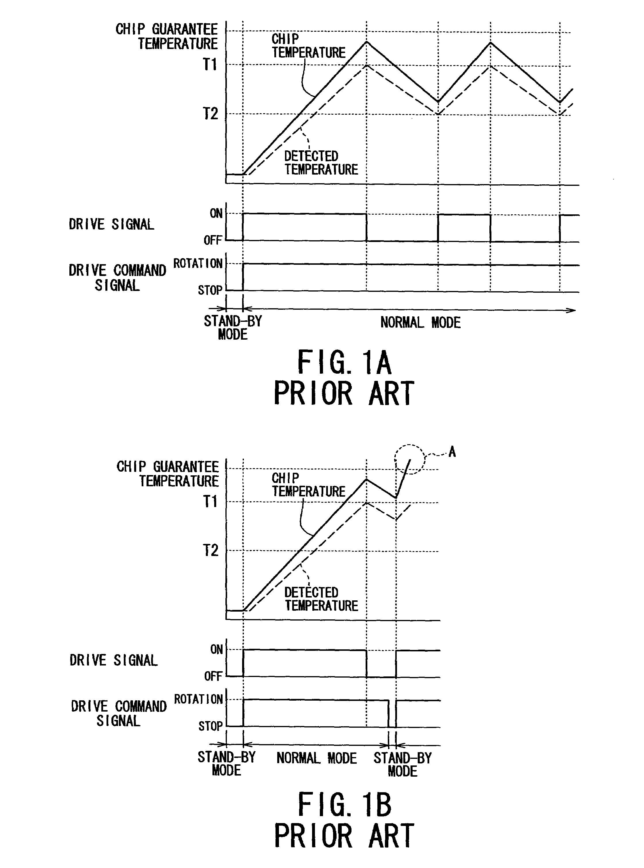
However, the switching elements, which were turned off once, is again subjected to its on-operation when the detected temperature reduces down to the release temperature T2, whereby the chip temperature is limited to temperature less than its guarantee temperature.
Hence the drive control circuit is reset, which loses the information indicative of states of the overheat protection control carried out before the shutdown.
However, the blower switch is manually turned on and off in sequence after the detected temperature reached the protective temperature T1, there will be caused a fear that the chip temperature is beyond a guarantee temperature of the chips (refer to a range shown by a reference “A” in FIG. 1B).
However, the means according to 1) is disadvantageous in that unfavorable conditions, such as higher surrounding temperature, will lead to frequent stops of the blower fan under the overheat protecting operation even in the normal use, thus spoiling user's amenity.
Further, means according to 2) and 3) are difficult to employ, because a greater increase in the production cost of the system is inevitable.

Method used


Image

  • Load drive control apparatus with performances of power-consumption reduction and overheat protection
  • Load drive control apparatus with performances of power-consumption reduction and overheat protection
  • Load drive control apparatus with performances of power-consumption reduction and overheat protection

Examples


first embodiment

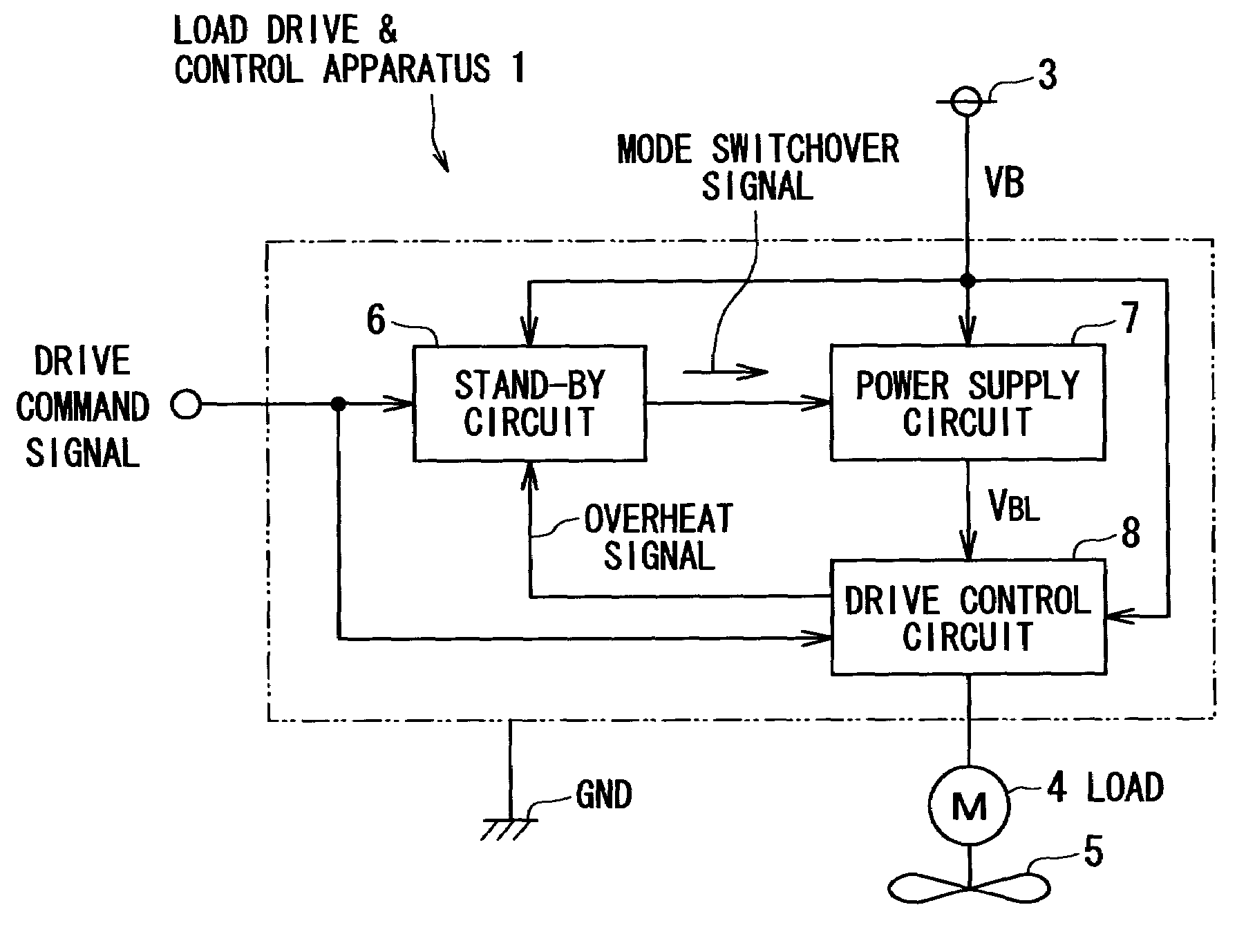
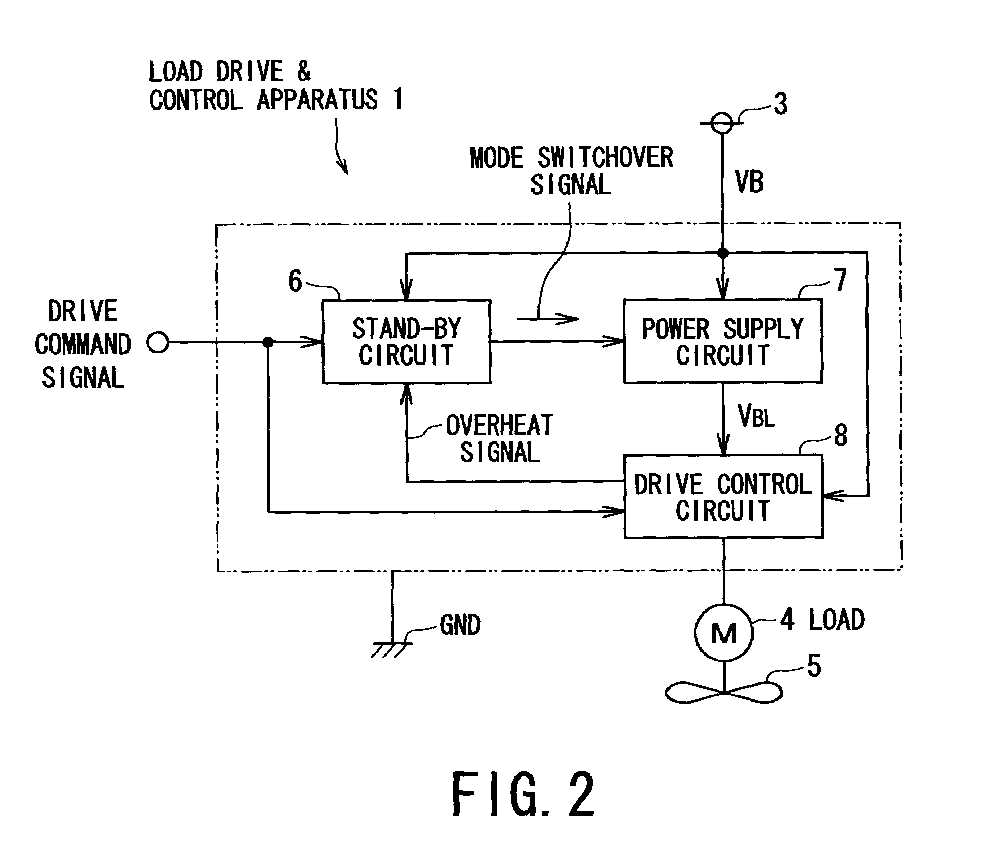
[0038]Referring to FIGS. 2 to 5, a first embodiment of the present invention will now be described, in which a load drive control apparatus according to the present invention is applied to the drive of an air conditioner mounted to a vehicle.

[0039]FIG. 2 shows an entire functional configuration of the load drive control apparatus 1. As shown in FIG. 2, the load drive control apparatus 1 is placed to drive the rotation of a brushless motor 4 (hereafter referred to as a motor) that serves as a load for the apparatus 1. Specifically, the load drive control apparatus 1 receives a battery voltage VB from a battery 2 (refer to FIG. 4) via a power supply line 3 and the ground GD and control of the motor 4 based on a drive demand signal (functioning as a control signal of the present invention) given by a not-shown ECU of the air conditioner.

[0040]The motor 4 has a rotating shaft to which a blower fan 5 (hereafter referred to as a fan) 5 of the car air conditioner is coupled. The fan 5 is a...

second embodiment

[0081]Referring to FIGS. 6 and 7, a second embodiment of the load drive control apparatus according to the present invention will now be described. In the following embodiments, for the sake of simplified explanation, the identical or similar constituents employed by the foregoing first embodiment are referenced using the same numerals.

[0082]The load drive control apparatus according to the second embodiment uses the same configuration as one employed by the foregoing first embodiment, except the stand-by circuit. The second embodiment uses a stand-by circuit 50 shown in FIG. 6. As shown in FIG. 6, the OR gate 22, which is placed between the comparator 21 and the charge / discharge switchover circuit 23 in FIG. 4 illustrating the first embodiment, is omitted. The remaining of the stand-by circuit 50 shown in the FIG. 6 is the same as that used in FIG. 4. Accordingly, since the overheat signal is not taken into the stand-by circuit 50.

[0083]Instead of the above configuration, the contr...

third embodiment

[0090]Referring to FIGS. 8 and 9, a third embodiment of the present invention will now be described.

[0091]FIG. 8 outlines the entire configuration of a load drive control apparatus 60, in which there are provided the stand-by circuit 50 that has been explained in the second embodiment and a drive control circuit 61.

[0092]The drive control circuit 61 is made of a low-power-consumption type of circuit, whose entire circuitry or whose only digital processing part is manufactured through the CMOS process. This drive control circuit 61 is internally and integrally provided with a digital circuit for control, a memory, and a power supply circuit which was separate from the drive control circuit as shown in FIG. 1. Accordingly, the drive control circuit 61 consumes less power compared to, at least, the circuitry of the drive control circuit 8 shown in FIG. 2.

[0093]An operation carried out cooperatively by both of the stand-by circuit 6 and the drive control circuit 61 will now be described...


PUM


Abstract

A load drive control apparatus comprises a drive control circuit and a mode switchover circuit. The drive control circuit, which operates under a driving power, for driving / controlling a load on a control signal. The drive / control of the load includes an overheat protection control with a hysteresis characteristic carried out on a temperature of a component of the drive control circuit and / or the load. The overheat protection control involves a drive-limiting operation to stop a drive of the load. The mode switchover circuit switches over the drive control circuit between a normal mode and a stand-by mode responsively to the control signal. The stand-by mode is less in driving power consumption than the normal mode. The stop of the drive of the load is maintained during the drive-limiting operation whatever the control signal indicates, as long as the temperature is higher than a lower limit of the hysteresis characteristic.

Description

BACKGROUND OF THE INVENTION[0001]1. The Field of the Invention[0002]The present invention relates to an apparatus for driving and controlling a load that operates on an electric power source, and in particular, to the apparatus that has the capability of not only reducing electric power consumed by the load but also protecting an overheat occurring in the load and / or the apparatus.[0003]2. Related Art[0004]An apparatus for driving and controlling a load (hereafter, referred to as a “load drive control apparatus”) has been used widely by various types of equipment. Such an apparatus is applied to, for example, a blower motor and a cooling fan motor, which are incorporated in an air conditioner mounted on an automobile. Both of the blower motor and cooling fan motor are loads to be driven and controlled by the load drive control apparatus.[0005]In such a system, it is required that electric power unnecessarily consumed by the motors during their non-operating periods of time is suppre...

Claims


Application Information

Patent Timeline
IPC IPC(8): H02H5/04H02J1/00H03K17/00H03K17/08H03K17/082
CPCH03K17/0822H03K2217/0036H03K2017/0806
Inventor WATANABE, HIDEOITO, MAKOTO
Owner DENSO CORP
Learn More