Active gate clamp circuit for self driven synchronous rectifiers

a synchronous rectifier and gate clamp technology, applied in the direction of electric variable regulation, process and machine control, instruments, etc., can solve the problems of failure of the device, different voltages of electronic devices, and destruction of the fet, so as to reduce the cost, the effect of reducing the time delay and reducing the power loss

Inactive Publication Date: 2006-08-08
TEXAS INSTR INC
View PDF15 Cites 7 Cited by
  • Summary
  • Abstract
  • Description
  • Claims
  • Application Information

AI Technical Summary

Benefits of technology

[0013]The present invention solves the foregoing problems and provides a synchronous self-driven converter in which a gate voltage is clamped to less than the maximum rated voltage. This is achieved by a clamp circuit using a small field effect transistor (FET) connected as a source follower in series with the gate of the synchronous rectifier FET. The gate voltage of the clamp FET is connected to a voltage source. The clamp limits the source lead of the clamp FET, which is connected to the gate of the synchronous rectifier FET, to the difference between the voltage source and the threshold voltage of the gate of the clamp FET. The clamp operates by effectively opening a switch in series with the ...

Problems solved by technology

However, various components in the electronic devices may require different voltages than is supplied by the power supply.
A problem with the foregoing circuit is that the secondary voltage from the transformer 24 appears directly across the gate-to-source of both of the rectifier elements 28 and 30.
This leads to destruction of the FET and failure of...

Method used


Image

  • Active gate clamp circuit for self driven synchronous rectifiers
  • Active gate clamp circuit for self driven synchronous rectifiers
  • Active gate clamp circuit for self driven synchronous rectifiers

Examples


Embodiment Construction

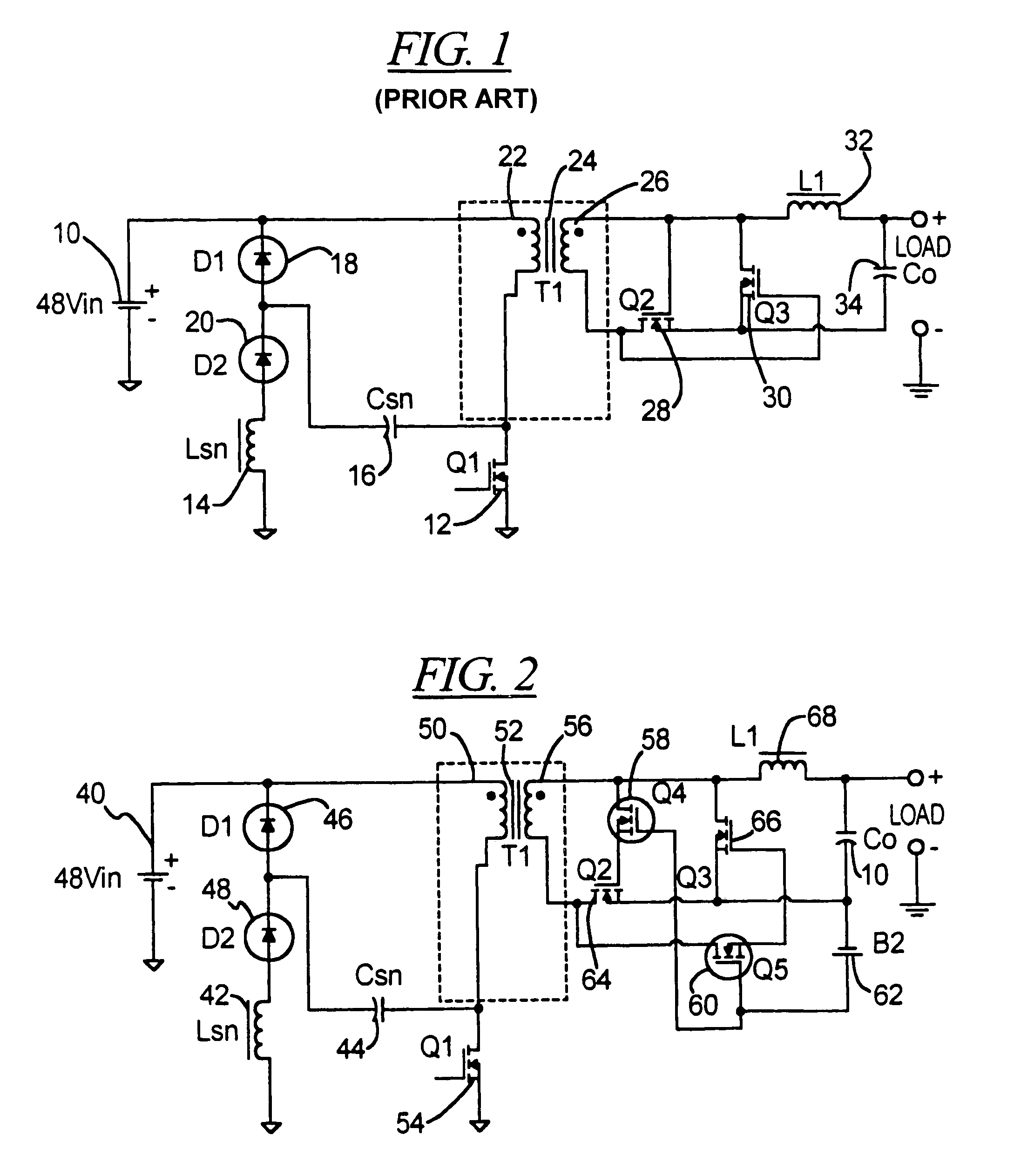
[0023]Referring to FIG. 2, an input voltage 40, which is supplied, for example, by a power supply unit of an electronic device, is provided at an input of a resonant primary snubber circuit including an inductor 42, capacitor 44 and diodes 46 and 48. These are connected to a primary side 50 of an isolation step-down transformer 52. A power switch in the form of a transistor 54 is also provided on the primary side 50. Although this circuit arrangement is shown for the primary side, other circuit arrangements are also possible. For example, resonant reset circuits, both active and passive, on either primary or secondary side of the transformer 51 are possible, as well as different topologies such as a two-transistor forward converter topology. For example, the converter may have a feedback loop connected to the primary side for regulation.

[0024]On a secondary side 56 of the transformer 52, transistors 58 and 60 have been added to the circuit of FIG. 1. The gates of the transistors 58 ...


PUM


Abstract

A DC-DC converter circuit includes a transformer with a resonate filter or snubber connected at a primary side and a switch for controlling operation of the converter. A secondary side of the transformer includes self-driven synchronous rectifiers and an output filter. Transistors are provided at the gates leads of the rectifiers and themselves are provided with a fixed voltage at their gates so as to clamp the peak voltages across to the rectifiers.

Description

BACKGROUND OF THE INVENTION[0001]1. Field of the Invention[0002]The present invention related generally to DC-DC voltage converters and, in particular, to synchronous rectifying DC voltage converters.[0003]2. Description of the Prior Art[0004]Electronic devices are generally supplied with power from a power supply unit that converts AC line power to a DC voltage. However, various components in the electronic devices may require different voltages than is supplied by the power supply. In addition, some of these components require a highly regulated voltage to operate properly. DC to DC converters are used to convert the output of the power supply unit to a different, regulated voltage.[0005]Electronic devices which may use DC to DC converters are computers, network cards, DSL (Digital Subscriber Line) cards, and the like. The DC to DC converters may be required to produce a 5 volt regulated output, or in some cases a 3 volt regulated output, 12 volt regulated output or 15 volt regula...

Claims


Application Information

Patent Timeline
IPC IPC(8): H02M7/217H02M3/07H02M1/34H02M3/335
CPCH02M1/34H02M3/33592Y02B70/1491Y02B70/1475H02M2001/346H02M1/346Y02B70/10
Inventor PRIEGNITZ, ROBERT A.DEVRIES, JR., CHARLES A.
Owner TEXAS INSTR INC
Why Eureka
Try Eureka