Relax gas discharge laser lithography light source

a laser lithography and gas discharge technology, applied in the direction of instruments, optical radiation measurement, active medium materials, etc., can solve the problems of depth of focus, the embodiment proposed is not workable, and the lowering of laser output caused by bandwidth narrowing can be limited to a small valu

Inactive Publication Date: 2006-08-08
CYMER INC
View PDF196 Cites 45 Cited by
  • Summary
  • Abstract
  • Description
  • Claims
  • Application Information

AI Technical Summary

Problems solved by technology

It is well known in the art of semiconductor manufacturing that depth of focus (“DOF”) is an important issue.
In addition, lowering of laser output caused by bandwidth narrowing can be limited to a small value because the bandwidth-narrowing device is disposed between the reflecting mirror and the output mirror.By using the present projection aligner, it was confirmed that the depth of focus of fine patterns increased in the same way as the first embodiment.
Yan also proposes the generation of three output beams from a single laser system, but the embodiment proposed is not workable.

Method used


Image

  • Relax gas discharge laser lithography light source
  • Relax gas discharge laser lithography light source
  • Relax gas discharge laser lithography light source

Examples


Embodiment Construction

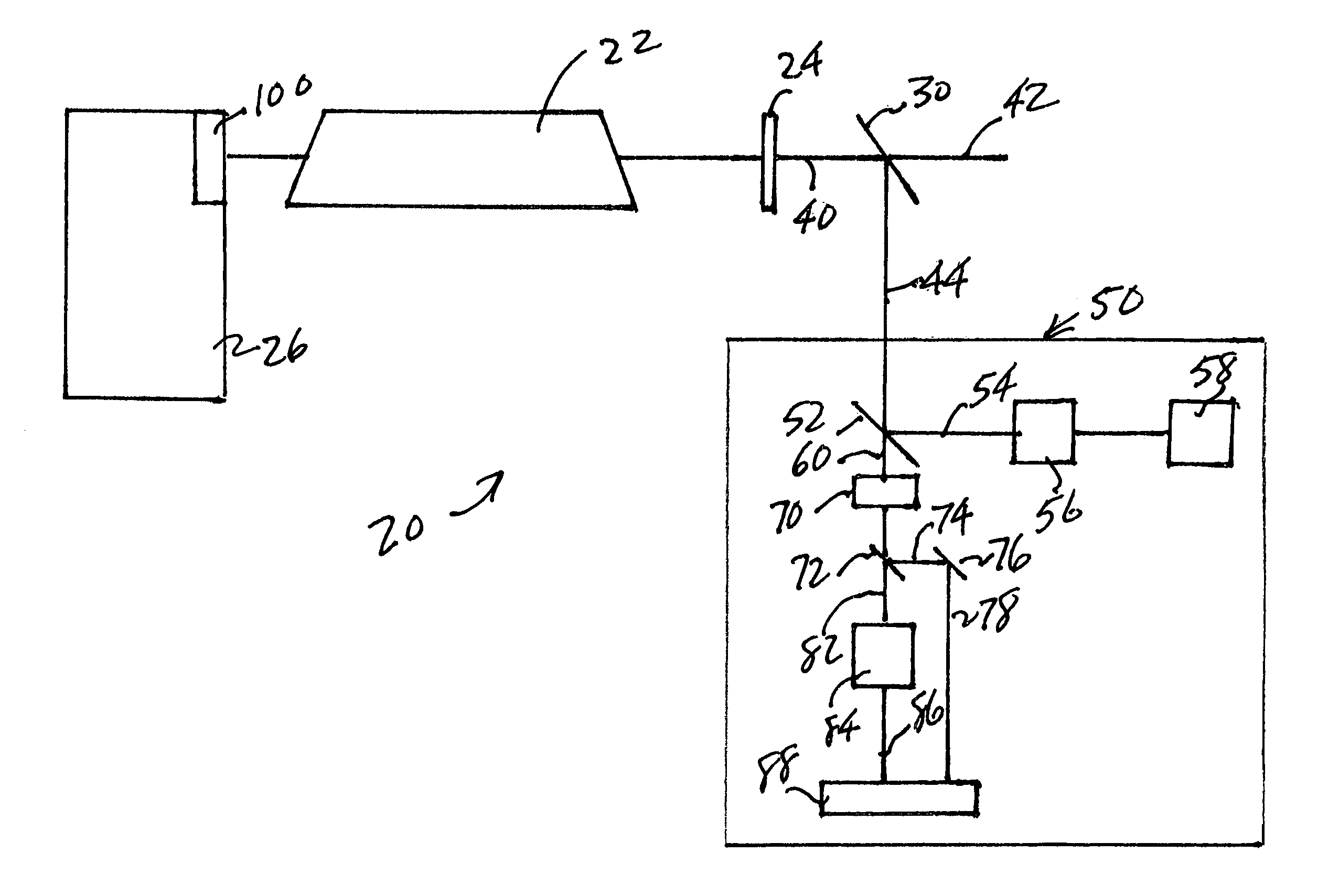
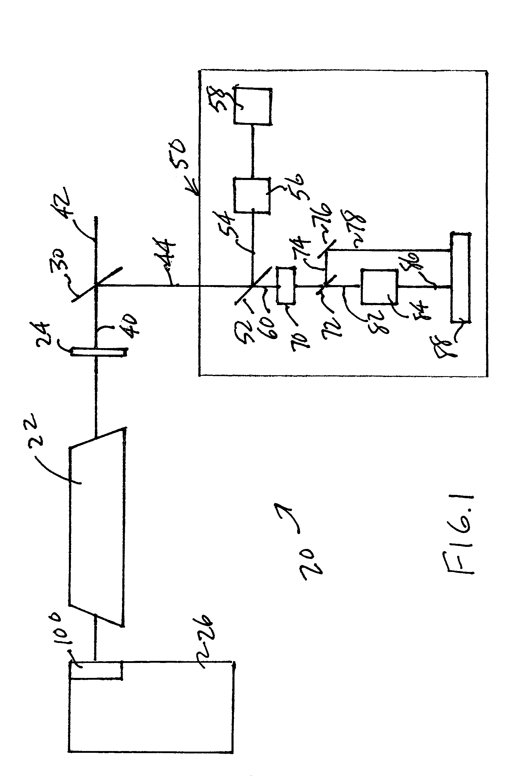
[0037]Turning now to FIG. 1 there is shown a RELAX laser output light pulse producing system 20 which may comprise, e.g., a laser chamber 22, an output coupler 24 and a line narrowing module 26, together forming a resonant laser oscillator. An output laser light pulse beam 40 comprising pulses in bursts of pulses, e.g., several hundred pulses per burst, at a selected pulse repetition rate and pulse energy. Such a beam of pulses may be passed through a beam splitter 30, which may serve to reflect a small portion of the output laser light pulse beam comprising a diagnostic laser light pulse beam 44, e.g., about 5%, into a metrology package 50, with the remainder forming a laser system 20 laser output light pulse beam 42. Within the metrology package, a further beam splitter 52 may serve to split the beam 44 into a portion 54 that enters a homogenizer 56 followed by a power meter 58. The unreflected portion 60 of beam 44 passing through the beam splitter 52 is passed through a beam win...


PUM

PropertyMeasurementUnit
thickaaaaaaaaaa
insertion distanceaaaaaaaaaa
frequencyaaaaaaaaaa

Abstract

An apparatus and method are disclosed for operating a narrow band short pulse duration gas discharge laser output light pulse beam producing system, producing a beam comprising laser output light pulses at a selected pulse repetition rate, which may comprise: a dispersive center wavelength selection optic selecting at least one center wavelength for each pulse determined at least in part by the angle of incidence of the laser light pulse beam containing the respective pulse on the dispersive wavelength selection optic; a tuning mechanism operative to select at least one angle of incidence of a first spatially defined portion of the laser light pulse beam containing the respective pulse upon the dispersive center wavelength selection optic; and, the tuning mechanism comprising a variably refractive optical element defining a plurality of refractive angular displacements of the first spatially defined portion of the laser light pulse beam passing through the variably refractive optical element at one of a plurality of positions of incidence of the laser light pulse beam on the variably refractive optical element. The variably refractive optical element may comprise: a first generally flat face defining a surface of incidence for the laser light pulse beam; and, a second multifaceted or curved face defining a plurality of generally flat surfaces of exit or a continuously varying surface of exit for the laser light beam. Other aspects of pulse parameter metrology and pulse modulation control, including in response to signals from the utilization tool are disclosed, e.g., relating to proper dose control with differing center wavelength spectra.

Description

RELATED APPLICATIONS[0001]The present application is a continuation-in-part of co-pending application Ser. No. 10 / 701,280, filed on Nov. 3, 2003, entitled LASER SPECTRAL ENGINEERING FOR LITHOGRAPHIC PROCESS, which is a continuation of Ser. No. 09 / 918,773, Jul. 27, 2001, also entitled LASER SPECTRAL ENGINEERING FOR LITHOGRAPHIC PROCESS, now U.S. Pat. No. 6,671,294, and the present application is a continuation-in-part of Ser. No. 10 / 875,662, filed on Jun. 23, 2004, entitled LASER OUTPUT BEAM WAVEFRONT SPLITTER FOR BANDWIDTH SPECTRUM CONTROL, and is a continuation-in-part of Ser. No. 10 / 847,799, filed on May 18, 2004, entitled LASER OUTPUT LIGHT PULSE STRETCHER, and of Ser. No. 10 / 808,157, filed on Mar. 23, 2004, entitled DUV LIGHT SOURCE. OPTICAL ELEMENT IMPROVEMENTS, which is a continuation-in-part of Ser. No. 10 / 173,190, filed on Jun. 14, 2002, entitled GAS DISCHARGE ULTRAVIOLET WAVEMETER WITH ENHANCED ILLUMINATION, now U.S. Pat. No. 6,750,972, and the present application is a cont...

Claims


Application Information

Patent Timeline
Patent Type & Authority Patents(United States)
IPC IPC(8): H01S3/22B23K26/06B23K26/40G01J1/42G01J9/02G02B26/00G02B26/08G03F7/20H01SH01S3/00H01S3/1055H01S3/225
CPCB23K26/063G01J1/429G01J9/02G02B26/002H01S3/225G03F7/70041G03F7/70575H01S3/005G02B26/0875B23K2201/40H01S3/0057H01S3/1055B23K26/0622B23K2101/40
Inventor SANDSTROM, RICHARD L.PARTLO, WILLIAM N.BROWN, DANIEL J. W.YAGER, THOMAS A.ERSHOV, ALEXANDER I.RAFAC, ROBERT J.RYLOV, GERMAN E.
Owner CYMER INC
Why Eureka
Try Eureka