Personal communication device with transmitted RF power strength indicator

Inactive Publication Date: 2006-08-08
VIA TECH INC
View PDF4 Cites 11 Cited by
  • Summary
  • Abstract
  • Description
  • Claims
  • Application Information

AI Technical Summary

Benefits of technology

[0014]It is an objective of the present invention to the transmitted RF signal power status, user-programmable warning signal in a form of sound, vibration or voice, and user-programmable when PCD gives warning signal for the PCDs' users. With such information, PCD user can adjust PCD position or change communication location to reduce PCD's radiated RF power or shorten the talk time to reduce the exposure time to RF radiation.
[0015]On the other words, the PCD of the present invention provides a TSSI (transmitted RF power strength indication) and a warning system for the PCDs' user. With such information, PCD user can adjust PCD position or change communication location to reduce PCD's radiated RF power or shorten the talk time to reduce the exposure time to RF radiation.

Problems solved by technology

Some scientific studies have shown that long-term exposure under the RF signal radiation could damage human tissue.
Because scientific studies show that long-term exposure to RF signal can damage human tissues.

Method used


Image

  • Personal communication device with transmitted RF power strength indicator
  • Personal communication device with transmitted RF power strength indicator
  • Personal communication device with transmitted RF power strength indicator

Examples


first embodiment

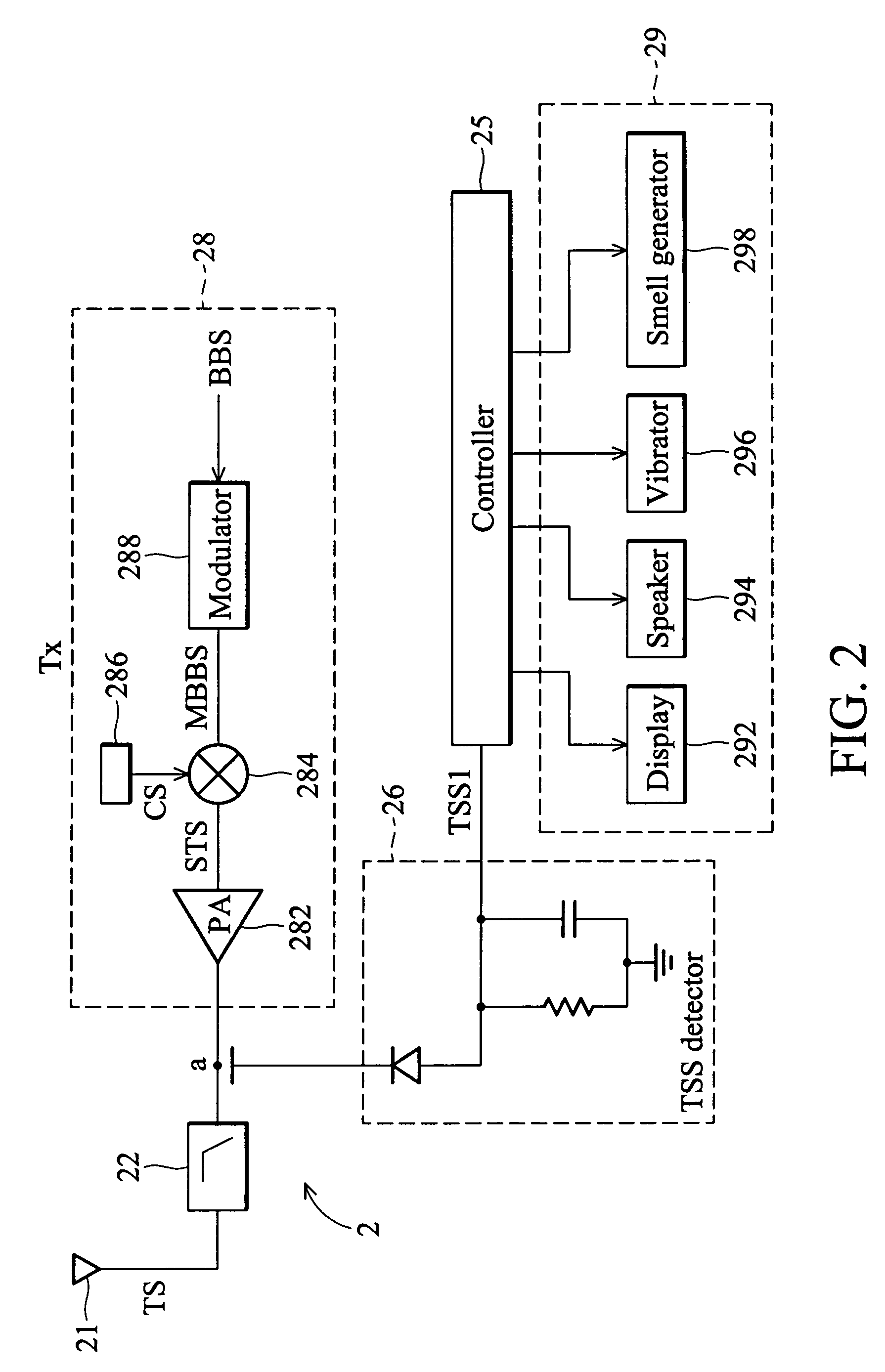
[0025]FIG. 2 is a block diagram of the first embodiment of the PCD with a transmitted RF power strength indicating circuit in the present invention. Transmitter 28 can be seen generally as depicted in FIG. 2, it included a modulator 288, a power amplifier 282 and a transmitted RF power detector 26. The transmitted baseband signal BBS is modulated at modulation section 288, and the output signal of modulation section MBBS is further processed then connected to the power amplifier 282 or connected to the power amplifier 282 directly. The power amplifier 282, as named, amplifies the power of the output signal. The amplified output signal is then filtered by a filter 22 and fed to the antenna 21 for signal radiation. The transmitted RF power detector (or called transmitted signal strength detector) detects TSS (transmitted signal strength) or the power of the amplified output signal.

[0026]In other words, the PCD 2 of the present invention mainly comprises a RF transmitter(TX) 28 a TSS d...

second embodiment

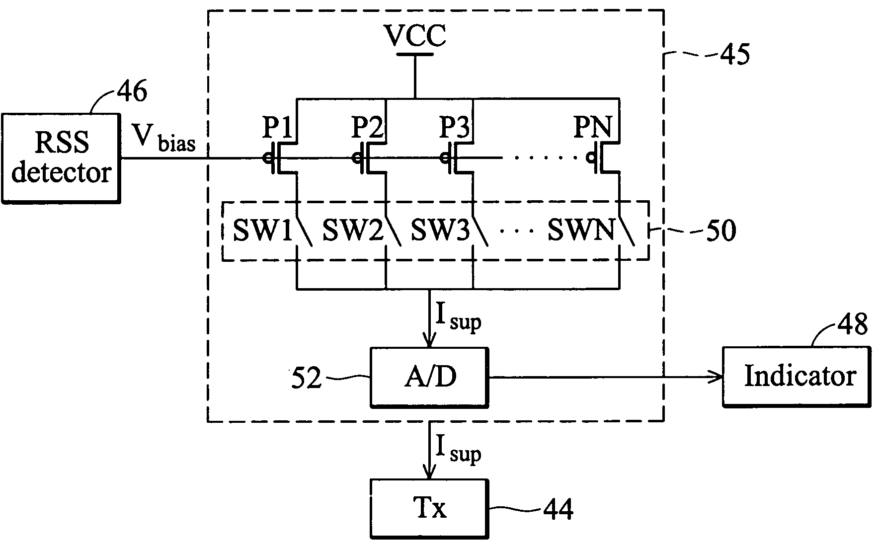
[0030]FIG. 3 is a block diagram of the second embodiment of the PCD with a transmitted RF power strength indicating circuit in the present invention. The second embodiment is similar to the first embodiment except the TSS detector 36. The transmitted signal strength TSS can be determined by sensing PA's (Power amplifier 382) dc current consumption as shown in FIG.3.

[0031]The transmitted RF power detector 36 (or called transmitted signal strength detector) is used to detect the TSS (transmitted signal strength) level. Once the TSS is detected, the detection result TSS2 will be sent to the controller 35, the controller will display corresponding TSS status in LCD or LED and deliver a user-programmable warning signal in a form of smell, sound, vibration, light or voice etc. to the PCD user. It is also user-programmable when a PCD generates the warning signal.

[0032]With the TSS status information, the PCD user can adjust their PCD position or change communication location to reduce the ...

third embodiment

[0035]FIG. 6 is a flow chart for indicating a transmitted RF power strength according to the present invention. The present invention also provides a method to indicating a transmitted RF power strength status of a transmitter for warning a PCD's user of high RF radiation. The method includes the following steps

[0036]Pre-set a warning level for the transmitted RF power strength as shown in step 602, for example, in dBm scale. Generally, a GSM handset emits RF radiation with a power range from −5 to 33 dBm. FIG. 5 is a graph of setting a warning level for the transmitted RF power strength in the present invention. In this example, we set 10 dBm as the pre-set warning level.

[0037]Detect the TSS level as shown in step 604. The detection method and apparatus can be found from the previous two embodiments.

[0038]If the TSS level is greater than the warning level, then execute the step (d), else execute step (b) as shown in step 606. Output the TSS level to the indicating device as shown i...


PUM


Abstract

A radio communication system for communication between a first mobile system and a second mobile system. Each mobile system has a transceiver for receiving and emitting radio signal. The second mobile system comprises a received signal strength detecting device, a power controller and an indicating device. The received signal strength detecting device detects a received signal strength of the transceiver in the second mobile system. The power controller outputs a transmitted power strength status and controls transmitted power of the transceiver according to the received signal strength. The indicating device receives the transmitted power strength status and indicates a transmitted RF power strength status of the transceiver in the second mobile.

Description

CROSS-REFERENCE TO RELATED APPLICATION[0001]This application is a continuation-in-part of prior application Ser. No. 10 / 223,246, filed Aug. 20, 2002.BACKGROUND OF THE INVENTION[0002]1. Field of the Invention[0003]The present invention relates generally to a radio communication system, and more particularly, to a PCD (Personal Communication Device) and a method capable of indicating the transmitted RF power strength level of a radio communication terminal by outputting the power strength level of a transmitter of the radio communication terminal to an indicating device.[0004]2. Description of the Related Art[0005]AMPS, PHS, NADC, GSM, DCS, PCS, IS-95, CDMA, WCDMA, DECT, WLAN (802.11), DECT, CT0, CT1, . . . etc. are well known standards for wireless network and PCDs(personal communication devices). Personal communication devices include cellular phones, cordless phones, PDAs, walkie-talkies, smart phones and others. All personal communication devices mentioned above are wireless commu...

Claims


Application Information

Patent Timeline
IPC IPC(8): H04Q7/20H04M1/00H04B1/04H04B1/38H04B7/005H04B7/26H04W52/10H04W52/52
CPCH04B1/3838H04W52/10H04W52/52H04B2001/3844
Inventor SHIH, DID-MINCHEN, CHUN-CHIEHHO, BING-MING
Owner VIA TECH INC
Why Eureka
Try Eureka