
3D printing apparatus using a beam of an atmospheric pressure inductively coupled plasma generator

a technology of inductively coupled plasma and 3d printing, applied in the field of additive manufacturing, can solve the problems of affecting the commercialization of additive manufacturing, the instrument for implementing such nanoparticles in the 3d manufacturing process has not yet been developed, and the protective layer cannot be easily covered. it can achieve the effects of enhancing thermal characteristics, reducing the diameter of nanoparticles, and increasing the surface energy density

Active Publication Date: 2020-08-04
GLUKHOY YURI +6
View PDF14 Cites 1 Cited by
  • Summary
  • Abstract
  • Description
  • Claims
  • Application Information

AI Technical Summary

Benefits of technology

The patent text describes how the use of nanoparticles in a process called sol-gel nanotechnology can affect the surface energy and thermal characteristics of the material being deposited. This can reduce the amount of RF power needed to vaporize the material, resulting in cost savings for manufacturers.

Problems solved by technology

This is a problem of the 450 mm-wafer processing that hinders its commercialization.
If flat surfaces can be protected from the plasma-chemical corrosion by DC plasma spraying with yttrium oxide (Y2O3), gas holes of showerheads with a diameter of 0.6 mm and a depth of 12 mm cannot be easily covered with such a protective layer and will be subject to plasma-chemical corrosion.
A challenge here is a 3D deposition of a thin-film impermeable electrolyte with a submicron thickness on the porous anode.
In spite of an advantage of refractory-material nanoparticles for the additive manufacturing, the instruments for implementation of such nanoparticles in a 3D manufacturing process have not been yet developed.
Nowadays, no one can perform building of 3D objects from refractory-material nanopowders because all refractory precursors for such a process will request melting, vaporization, precise delivery to the object, distribution in patterns, and subsequent layer-by-layer sintering of a multiple-layer structure from an amorphous state to a crystalline state.
For example, a laser that can provide a focused thermal energy for melting and consolidating a metal powder exposed to a laser beam and subsequent integration of the substance onto a 3D object does not possess energy sufficient to afford such a process if it uses a ceramic material.
Besides, a laser cannot carry the building material and deliver it in the melted or vaporized substance for densification of the 3D objects.
However, real 3D objects cannot be produced without transferring to nanoparticles a thermal energy sufficient for their melting and thus for subsequent post-deposition thermal processes, especially for melting, consolidation, and sintering.
If the process is still performed, the obtained 3D objects will suffer from such drawbacks as shrinking, low precision and low density.

Method used


Image

  • 3D printing apparatus using a beam of an atmospheric pressure inductively coupled plasma generator
  • 3D printing apparatus using a beam of an atmospheric pressure inductively coupled plasma generator
  • 3D printing apparatus using a beam of an atmospheric pressure inductively coupled plasma generator

Examples


Embodiment Construction

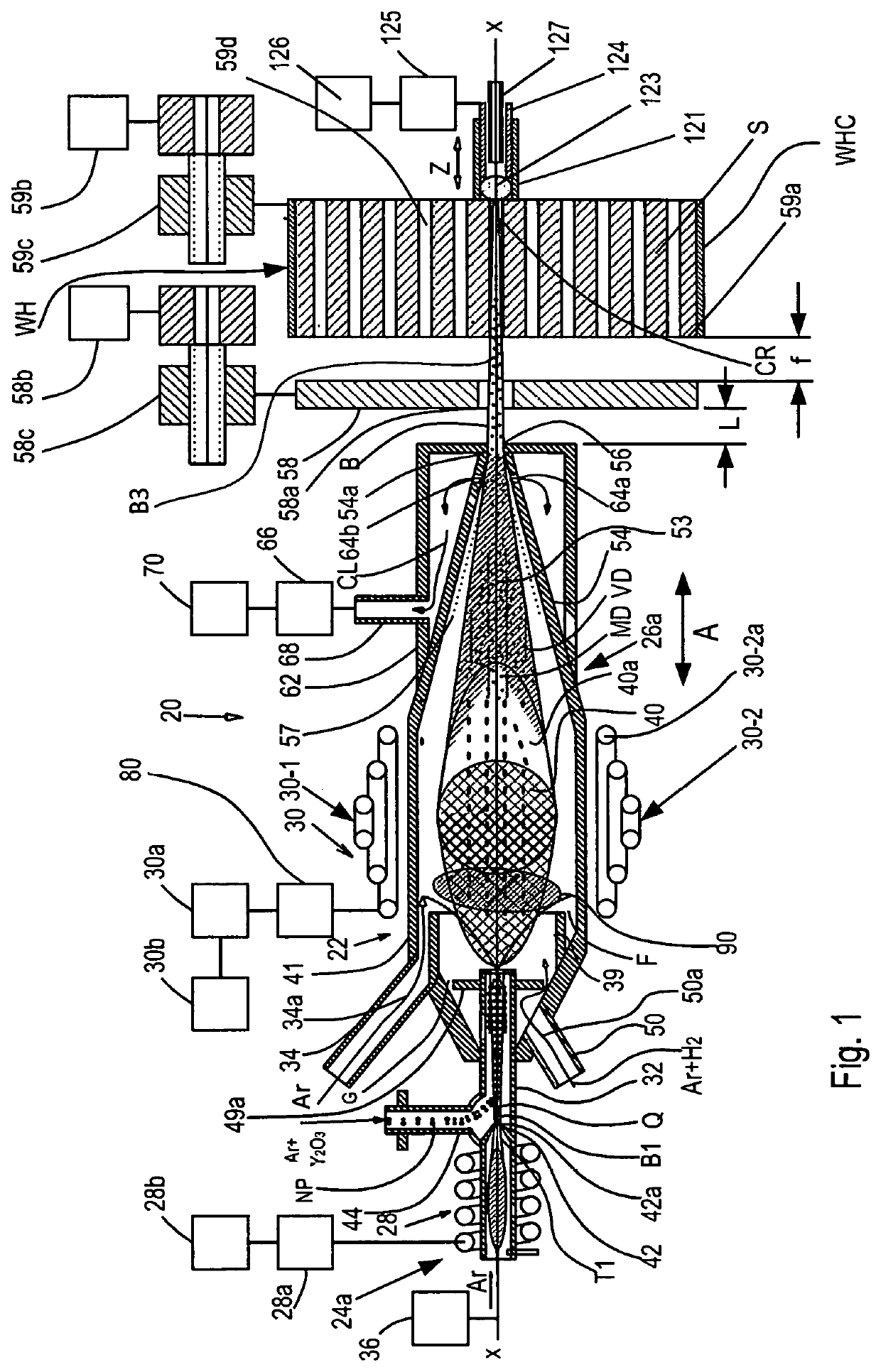
[0057]The present invention relates to the field of additive manufacturing. More specifically, the present invention relates to a 3D printing apparatus using nanoparticles as a building material for 3D objects and an atmospheric-pressure inductively coupled plasma (hereinafter ICP) generator of a plasma beam with appropriate devices for vaporizing, atomizing and forming precursor particles into a plasma beam focused onto an object being treated. The invention also relates to a method of 3D printing by using the 3D printing apparatus of the invention.

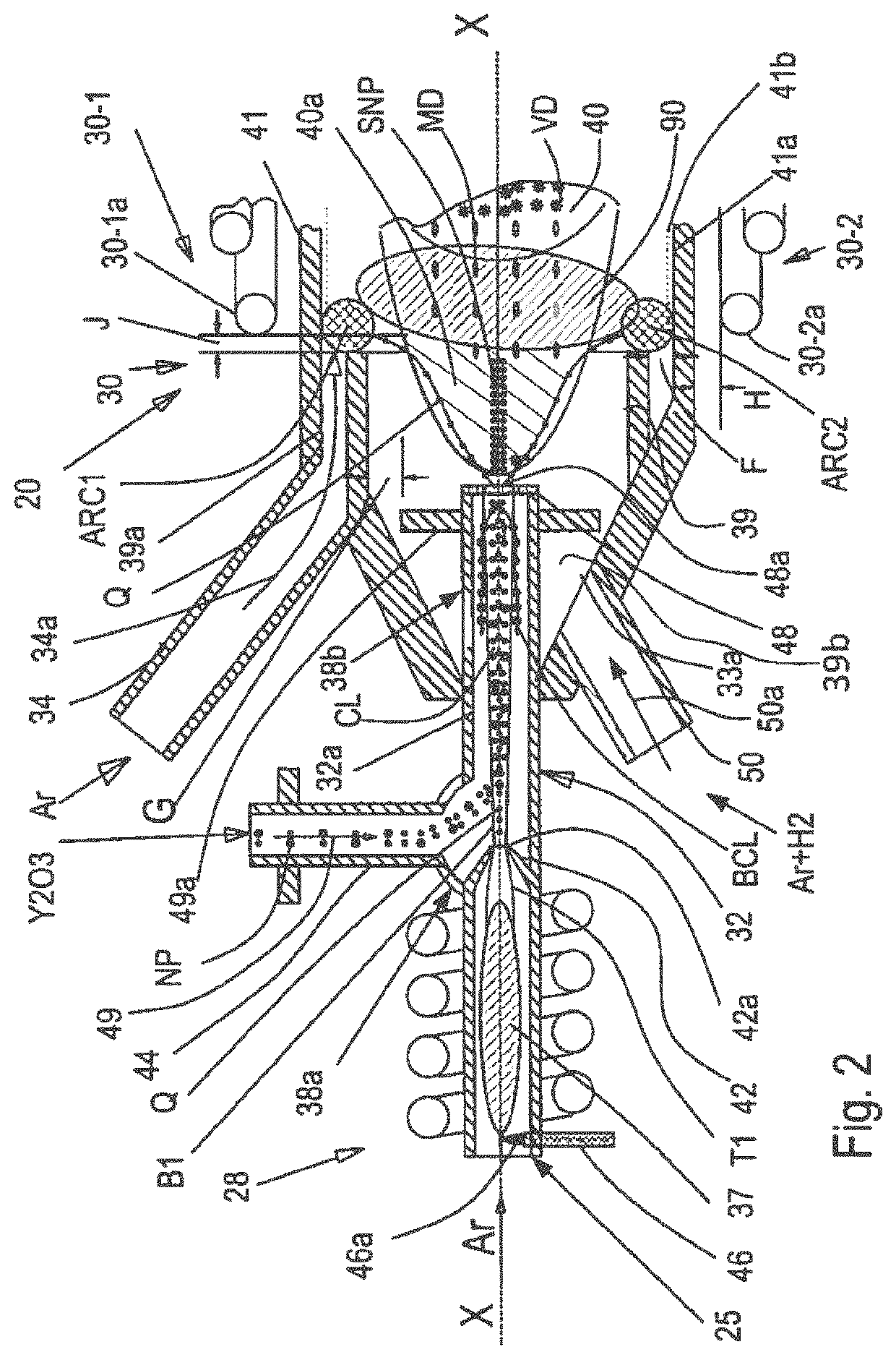
[0058]FIG. 1 is a longitudinal sectional view of an atmospheric-pressure inductively coupled plasma-beam generator (hereinafter referred to as a “plasma generator” or “ICP generator”) used in the 3D printer of the invention. As can be seen from FIG. 1, the plasma beam generator, which in an assembled form is designated by reference numeral 20, consists of two parts, i.e., a top plasma beam generator and a bottom plasma beam generator, an...


PUM

PropertyMeasurementUnit
diameteraaaaaaaaaa
depthaaaaaaaaaa
diameteraaaaaaaaaa

Abstract

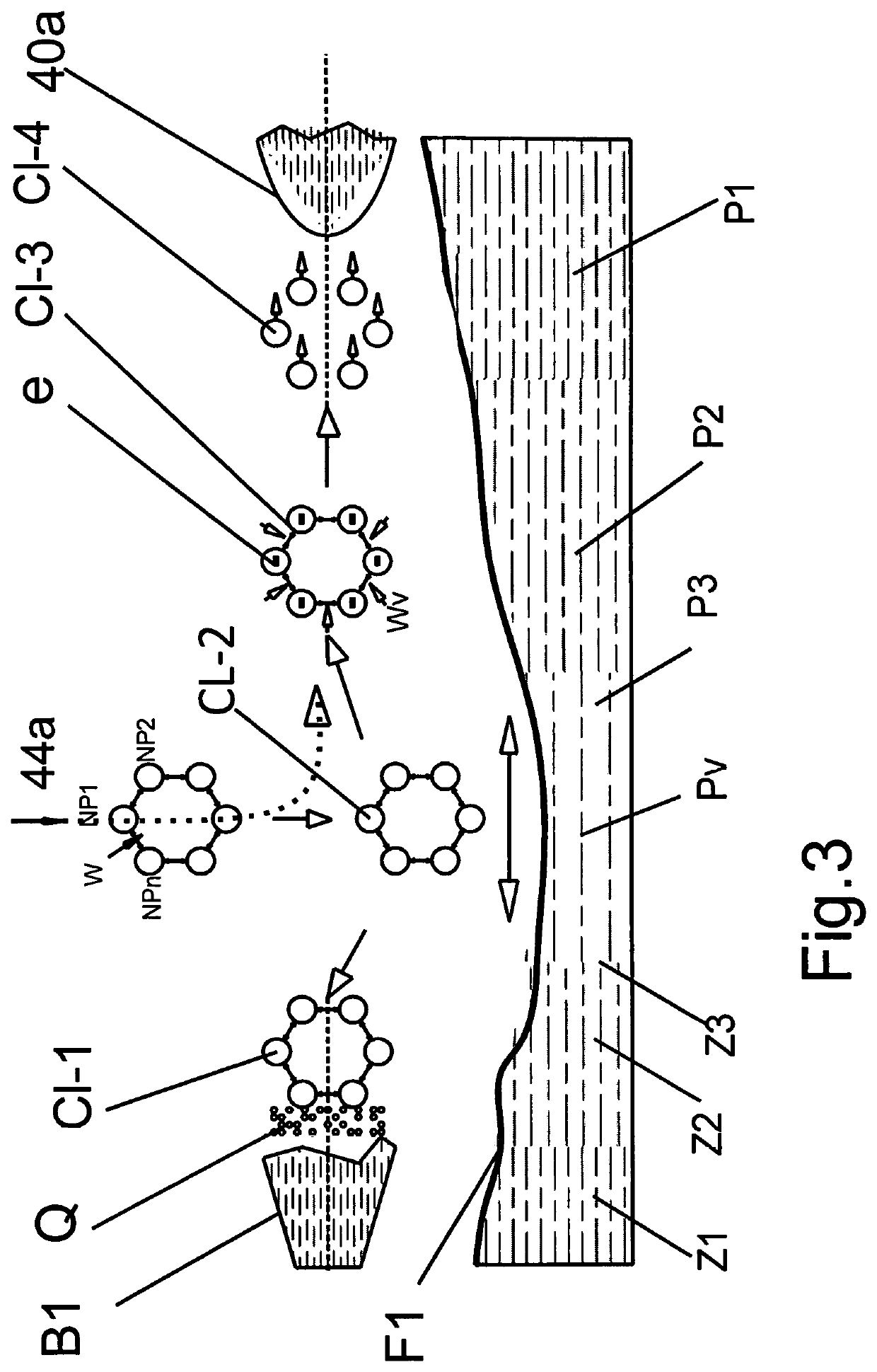
A 3D printer apparatus for printing a refractory materials on the surfaces of workpieces in accordance with a given program is disclosed. The apparatus contains a first generator for generating a first atmospheric ICP beam, a second generator for generating a second atmospheric ICP beam, and a bouncing tube between the generators for breaking clusters of precursor nanoparticles into elementary charged nanoparticles that penetrate in a premelted state into a plasma discharge formed in the second generator under the inductive coupling with a saddle antenna, which encompasses the second generator. The outlet nozzle of the second generator emits the second beam onto an extractor plate that is a part of a plasma gun, which converts the second beam into a finely controlled focusing beam capable of printing a material even on the inner surfaces of deep small diameter gas holes of showerheads.

Description

TECHNICAL FIELD[0001]The present disclosure relates to the fields of additive manufacturing. More specifically, the present disclosure relates to a three-dimensional (hereinafter referred to as “3D”) printing apparatus using a beam of an atmospheric pressure inductively coupled plasma generator with nanoparticles as a building material for 3D objects. The 3D printer of the invention also uses an atmospheric-pressure ICP generator of a plasma beam with appropriate devices for vaporizing, atomizing and forming the precursor particles into a beam focused onto an object being treated.BACKGROUND OF THE INVENTION[0002]Semiconductor industry demands fabrication of two types of 3D objects. One of them is an elevated-up large area 3D dielectric structure for electrostatic chucks. Having a plurality of fine hair-like modules, it grips large thin flat objects like a silicon wafer with the diameter of 450 mm. An electrostatic force applied to a grasped flexible wafer with a large area may bend ...

Claims


Application Information

Patent Timeline
Patent Type & Authority Patents(United States)
IPC IPC(8): B33Y10/00B29C64/209B29C64/159B29C64/241B29C64/245B29C64/25B29C64/264B33Y30/00
CPCB29C64/25B29C64/245B29C64/264B29C64/209B29C64/241B33Y30/00B29C64/371B29C64/159B33Y10/00Y02P10/25B22F2999/00B22F12/53B22F12/22B22F12/90B22F10/25B22F12/44B22F1/054B22F2202/13B22F10/10B22F10/20
Inventor GLUKHOY, YURIKERZHNER, TATIANARYABOY, ANNAKERZHNER, JOSHUARYABOY, MICHAELKERZHNER, ANDREWKERZHNER, KEVIN
Owner GLUKHOY YURI
Learn More