Confocal probe having scanning mirrors mounted to a transparent substrate in an optical path of the probe

a confocal probe and transparent substrate technology, applied in the field of confocal probes, can solve the problems of difficult rapid application of medical treatment, large sensitivity of the scanning mirror, and large sensitivity and achieve the effect of simple manufacturing and assembly process, excellent thermal characteristics, and small diameter of the confocal prob

Inactive Publication Date: 2007-08-07
HOYA CORP
View PDF29 Cites 12 Cited by
  • Summary
  • Abstract
  • Description
  • Claims
  • Application Information

AI Technical Summary

Benefits of technology

[0010]The present invention is advantageous in that a relatively small diameter of a confocal probe can be realized, manufacturing and assembling process can be simplified, and a confocal probe having excellent thermal characteristics can be provided.

Problems solved by technology

Such an examination requires a relatively long time, and it has been difficult to apply medical treatment quickly.
Therefore, the manufacturing process of the scanning mirrors and assembling process thereof tends to be complicated, which may increase manufacturing costs.
Therefore, when a relatively large thermal change occurs, a positional relationship of the optical system and the scanning mirrors is shifted, which causes the optical path of the scanning laser beam to be displaced.
Due to this relatively worse thermal characteristic of the probe, under a relatively high temperature around the probe, it is difficult to keep a precise location of the image.

Method used


Image

  • Confocal probe having scanning mirrors mounted to a transparent substrate in an optical path of the probe
  • Confocal probe having scanning mirrors mounted to a transparent substrate in an optical path of the probe
  • Confocal probe having scanning mirrors mounted to a transparent substrate in an optical path of the probe

Examples


first embodiment

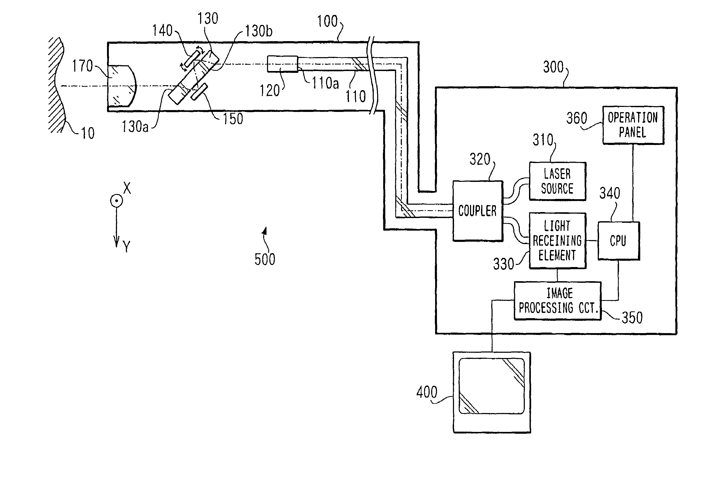
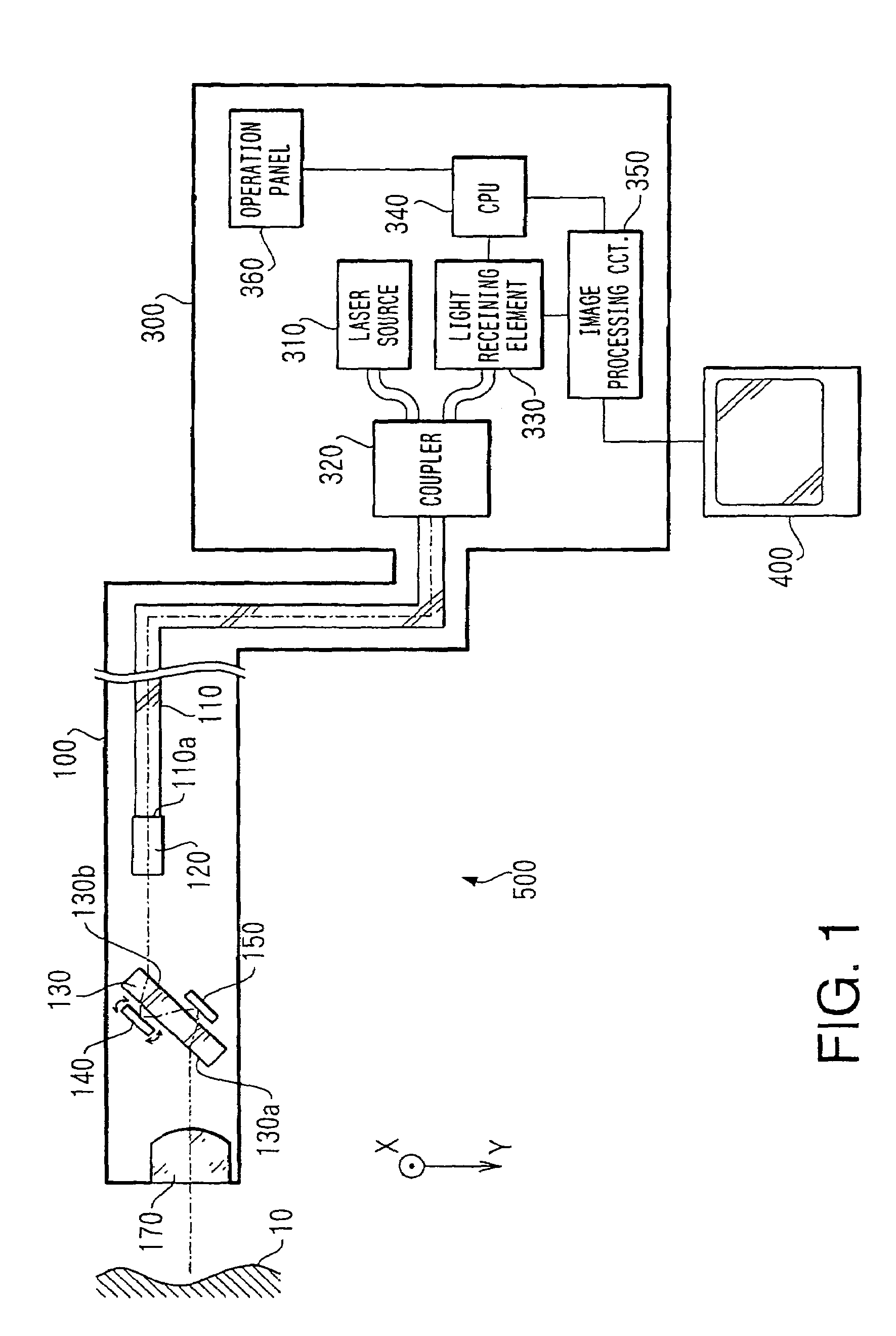
[0032]FIG. 1 shows a block diagram of a scanning type confocal probe device 500 according to the invention. The confocal probe device 500 includes a scanning type confocal probe unit 100, a processing unit 300 and a monitor 400.

[0033]The confocal probe unit 100 is inserted in a forceps channel of an endoscope (not shown), which is inserted in a human cavity. An image inside the human cavity (e.g., tissues) can be captured using the probe unit 100. The captured image is processed by the processing unit 300 and is displayed on the monitor 400.

[0034]As shown in FIG. 1, the processing unit 300 includes a laser source 310, a coupler 320, a light receiving element 330, a CPU (Central Processing Unit) 340, an image processing circuit 350 and an operation panel 360.

[0035]The laser source 310 according to the first embodiment emits an He-Ne laser having a wavelength of 421 nm. It is known that the shorter the wavelength of the laser beam is, the higher the resolution of the image is. It shou...

second embodiment

[0057]FIG. 3 is a block diagram showing a confocal probe device 500y according to the invention. In FIG. 3, the elements identical to those shown in FIG. 1 are given the same reference numerals, and description thereof will not be repeated.

[0058]The confocal probe device 500y includes a confocal probe unit 100y, the processing unit 300 and the monitor 400.

[0059]According to the confocal probe device 500y, only one micromirror is used to obtain a two-dimensional image of the tissues. In the confocal probe device 500y, a two-axis scanning type (which is capable of deflecting the laser beam both in the X direction and in the Y direction) micromirror 150y is employed instead of the second micromirror 150 of the first embodiment. Further, the first micromirror 140 of the first embodiment is replaced with a mirror (e.g., a single metal layer or multilayer coating of dielectric substance) 140y.

[0060]It should be noted that, in the structure shown in FIG. 3, the mirror 140y is formed on th...

third embodiment

[0061]FIG. 4 is a block diagram showing a confocal probe device 500z according to the invention. In FIG. 4, the elements identical to those shown in FIG. 1 are given the same reference numerals, and description thereof will not be repeated.

[0062]As shown in FIG. 4, the confocal probe device 500z includes a confocal probe unit 100z, a processing unit 300z and the monitor 400.

[0063]The processing unit 300z includes a laser source 310z having a Brewster window, through which polarized beam is emitted. The beam emerged from the Brewster window is an S-polarized beam with respect to a polarization layer 181, which will be described later.

[0064]The laser beam emitted by the laser source 310Z is incident on the optical fiber 110 of the confocal probe unit 100z through the coupler 320. The light beam transmitted through the optical fiber 110 is collimated by the GRIN lens 120 and is introduced to a polarization beam splitting cube 180.

[0065]The polarization beam splitting cube 180 has a pol...


PUM


Abstract

A confocal probe unit is provided with a scanning type confocal probe, which includes at least one scanning mirror, and a transparent substrate on which the at least one scanning mirror is mounted. The transparent substrate is inserted in an optical path of the confocal probe such that a light beam proceeding along the optical path is deflected by the scanning mirror.

Description

[0001]The present disclosure relates to the subject matters contained in Japanese Patent Application No. 2002-321322 and No. 2002-321323, both filed on Nov. 5, 2002, which are expressly incorporated herein by reference in their entireties.BACKGROUND OF THE INVENTION[0002]The present invention relates to a confocal probe to be employed in an endoscope device and a confocal endoscope device for observing tissues inside the human body and the like.[0003]Conventionally, when tissues of a human body are examined, parts of the tissues are cut using a treatment tool such as a forceps for cutting. Then, the cut parts of the tissues are examined. Such an examination requires a relatively long time, and it has been difficult to apply medical treatment quickly.[0004]Recently, a confocal optical scanning probe for non-invasive imaging has been known. Typically, the confocal probe is configured to illuminate tissues inside a human body with a scanning laser beam, and receives a reflected beam th...

Claims


Application Information

Patent Timeline
Patent Type & Authority Patents(United States)
IPC IPC(8): A61B1/06G02B26/08A61B1/04
CPCA61B1/00009A61B1/00096A61B1/00172A61B5/0068A61B5/0084A61B1/063
Inventor MIZUMO, ROGERIO JUN
Owner HOYA CORP
Why Eureka
Try Eureka