Discharge lamp lighting device

a technology of discharge lamp and discharge bulb, which is applied in the direction of lighting devices, light sources, instruments, etc., can solve the problems of reducing the luminous quantity of the power at turn-on, requiring more heat for evaporation, and bringing about voltage drop, so as to achieve precise attenuation control of output power, stable light emission, and low production cost

Inactive Publication Date: 2006-08-15
MITSUBISHI ELECTRIC CORP
View PDF20 Cites 3 Cited by
  • Summary
  • Abstract
  • Description
  • Claims
  • Application Information

AI Technical Summary

Benefits of technology

[0012]Thus, it offers an advantage of being able to provide a discharge bulb ballast capable of producing sufficient luminous quantity quickly and emitting appropriate luminous quantity when fillers vaporize, even when it is applied to a discharge bulb such as a mercury-less discharge bulb that uses metals requiring a large amount of heat to vaporize as the fillers.
[0032]Thus, it can carry out precise attenuation control of the output power even when the discharge bulb voltage immediately after switching on the light exceeds the turning point. Accordingly, it can output appropriate power even when the light is turned on in a condition in which the metal halides are evaporated and emitting light because of repetitive switching off and on. As a result, it offers an advantage of being able to implement a discharge bulb ballast applicable to HID bulbs without using mercury, which are used as the onboard headlights requiring the sharp start-up of the luminous quantity and stable light emission with little irregularities. In addition, it offers an advantage of being able to carry out precise attenuation control of the output power in spite of the fluctuations in the stable voltage of the discharge bulbs.

Problems solved by technology

The zinc or indium, however, requires more amount of heat for evaporation than mercury.
As for the conventional HID bulb using the mercury, the mercury, which quickly becomes gaseous, brings about a voltage drop.
In addition, since the quantity of light is limited to that emitted by the xenon gas, the luminous quantity is comparatively low for the power at turn-on.
As a result, the HID bulb cannot be supplied with appropriate power, and takes a considerable time until it produces a sufficient luminous quantity.
In particular, since the onboard headlights require sharp start-up of the luminous quantity, it is difficult for this purpose to use the conventional discharge bulb ballast.
In addition, when fillers vaporize, the luminous quantity increases sharply, which presents a problem in that the luminous quantity at the lighting up of the discharge bulb is unstable.

Method used


Image

  • Discharge lamp lighting device
  • Discharge lamp lighting device
  • Discharge lamp lighting device

Examples


embodiment 1

[0046]FIG. 1 is a block diagram showing a configuration of an embodiment 1 of a discharge bulb ballast in accordance with the present invention.

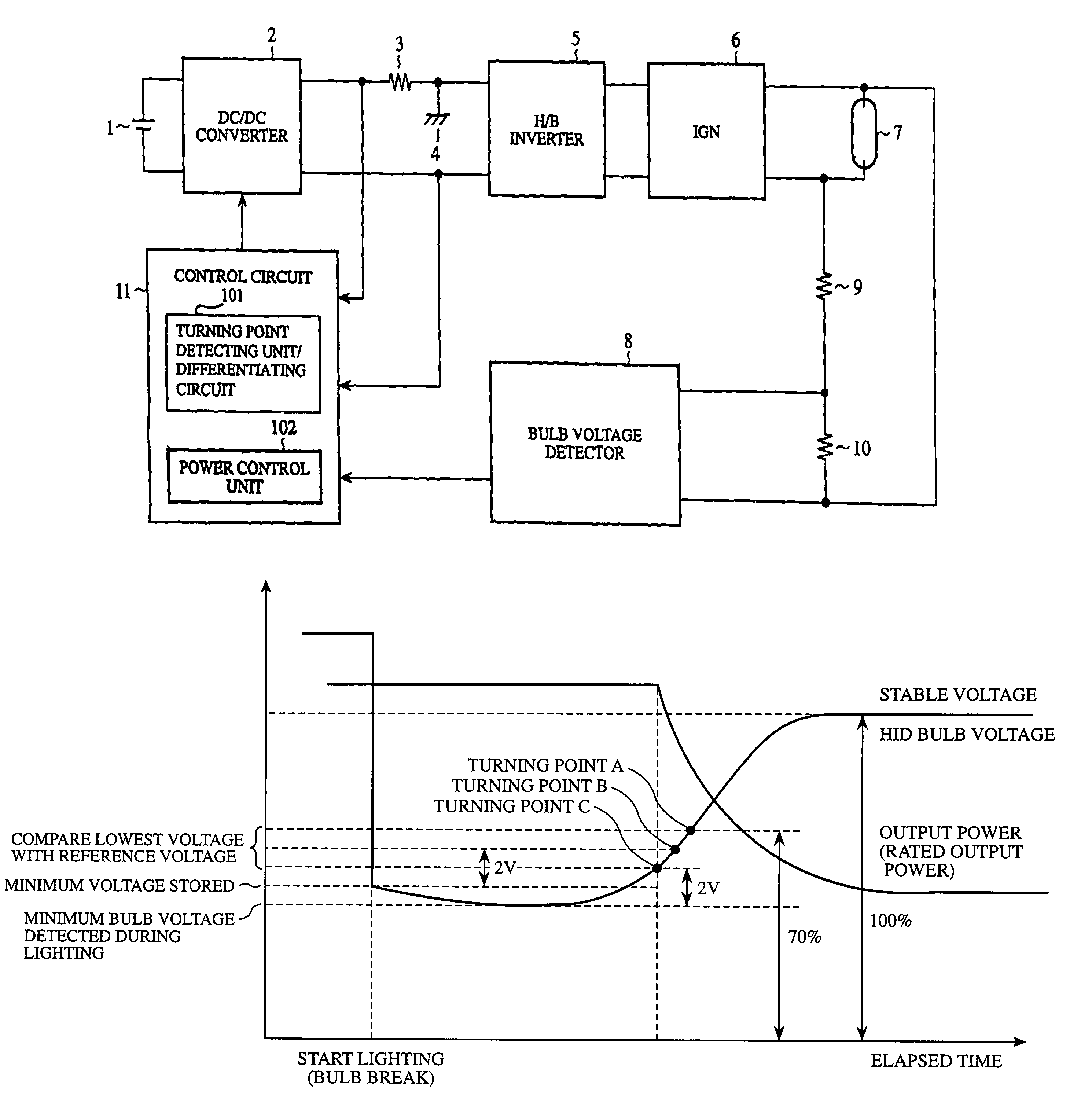
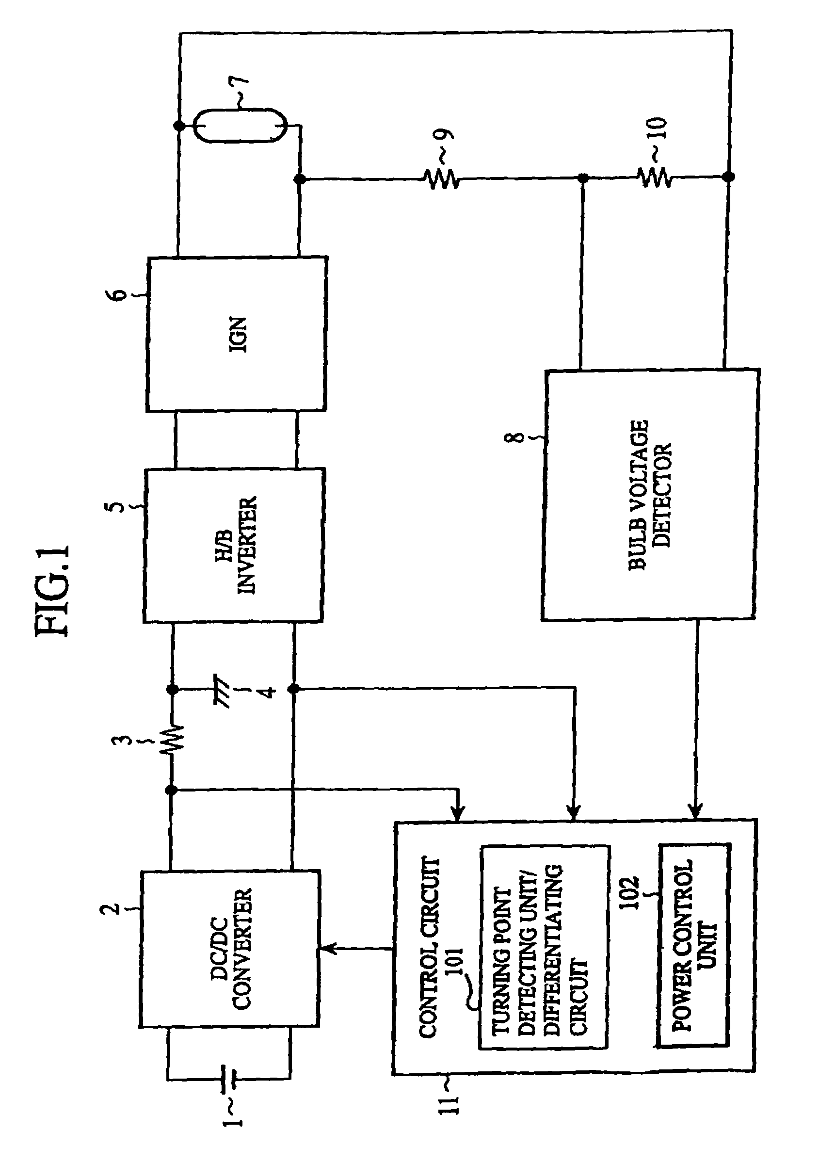
[0047]As shown in FIG. 1, the embodiment 1 of the discharge bulb ballast includes a power supply 1, a DC / DC converter 2, a current detection resistor 3, a ground terminal 4, an H / B inverter 5, an ignition circuit (IGN) 6, an HID bulb 7, a bulb voltage detector 8, resistors 9 and 10, and a control circuit 11.

[0048]The power supply 1 consists of a power supply such as an onboard battery. The DC / DC converter 2 is provided to boost the DC power supply voltage of the power supply 1. The current detection resistor 3 is provided to detect the current flowing from the DC / DC converter 2 to the H / B inverter 5, that is, to detect the current flowing into the HID bulb 7. The ground terminal 4 is provided for grounding an end of the current detection resistor 3 to the body of an automobile. The H / B inverter 5 is an inverter that uses an H-bridge circuit ...

embodiment 2

[0061]In the present embodiment, the turning point detecting unit 101 is composed of a differentiating circuit. The differentiating circuit can be composed of a dedicated piece of hardware, or of a program executed by a computer.

[0062]For example, a configuration is possible in which the control circuit 11 is composed of a computer, and the turning point detecting unit 101 and power control unit 102 are constructed by combining programs corresponding to their functions with the hardware such as a central processing unit and memory. The operation of the configuration is as follows.

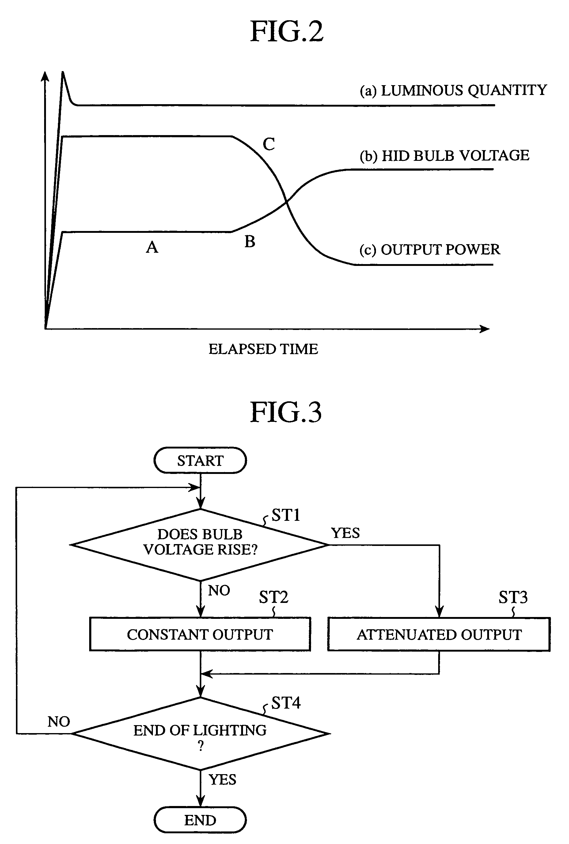
[0063]FIG. 3 is a flowchart illustrating the operation of the control circuit 11 composed of a computer.

[0064]First, the turning point detecting unit 101 makes a decision as to whether the HID bulb voltage is rising (step ST1). When the HID bulb voltage is not rising at step ST1, the processing proceeds to step ST2 at which the power control unit 102 controls the output power to become constant. The state c...

embodiment 3

[0067]In the present embodiment 3, the turning point detecting unit 101 is configured such that it sets the turning point at 70% of the stable voltage that is defined as the voltage in the state in which the lighting of the HID bulb 7 becomes stable and the HID bulb voltage is made stable. Since the remaining configuration of the discharge bulb ballast including the power control unit 102 is the same as that of the embodiment 1 as shown in FIG. 1, the description thereof is omitted here.

[0068]FIG. 4 is a diagram illustrating the HID bulb voltage and output power characteristics in a combination of the embodiment 3 of the starter in accordance with the present invention and the HID bulb without using the mercury.

[0069]The voltages of the HID bulbs, which are determined according to the components and pressure of the internal gases, have individual difference. Thus, a fixed turning point cannot cope with the HID bulbs with the variations. In view of this, the present embodiment sets t...


PUM


Abstract

A discharge bulb ballast has a control circuit (11) that includes a turning point detecting unit (101) for detecting a turning point at which a bulb voltage starts rising after switching on a discharge bulb (7). Immediately after switching on the discharge bulb (7), a power control unit (102) carries out control in such a manner that the discharge bulb (7) is supplied with first power. When the turning point detecting unit (101) detects that the voltage of the discharge bulb (7) exceeds the turning point, the power control unit (102) supplies the discharge bulb (7) with second power less than the first power.

Description

[0001]This Application is a National Phase Application under U.S.C. 371 claiming the benefit of PCT / JP03 / 08300 filed on Jun. 30, 2003, which has priority based on Japan Application No. 2002-193443 filed on Jul. 2, 2002.TECHNICAL FIELD[0002]The present invention relates to a discharge bulb ballast used for headlights of automobiles, for illumination lamps of indoor and outdoor facilities, warehouses and factories, and for streetlights.BACKGROUND ART[0003]Generally, discharge bulbs, particularly high-intensity discharge bulbs (HID bulbs) such as metal halide bulbs, high-pressure sodium bulbs and mercury bulbs have advantages of large luminous flux, high lamp efficiency and long life. Accordingly, they have been used as illumination lamps of indoor and outdoor facilities, warehouses and factories, and as streetlights. In particular, they are now employed as headlights of vehicles such as automobiles.[0004]An ordinary HID bulb utilizes gases such as xenon, metal halides and mercury in t...

Claims


Application Information

Patent Timeline
Patent Type & Authority Patents(United States)
IPC IPC(8): H05B37/02H05B41/288H05B41/38
CPCH05B41/2882H05B41/388H05B41/386H05B41/2883
Inventor OKURA, SUSUMUOHSAWA, TAKASHI
Owner MITSUBISHI ELECTRIC CORP
Why Eureka
Try Eureka