Method for characterization of laser pulses using pulse quality factor

a laser pulse and quality factor technology, applied in the field of characterizing laser pulses, can solve the problems of difficult to obtain phase information, not allowing to go much below, and detectors are very expensive instruments

Inactive Publication Date: 2006-08-15
UNIV LAVAL
View PDF2 Cites 1 Cited by
  • Summary
  • Abstract
  • Description
  • Claims
  • Application Information

AI Technical Summary

Benefits of technology

[0018]According to a second broad aspect of the present invention, there is provided method to predict analytically the evolution of a pulse temporal width as it propagates in a dielectric media causing a second-order dispersion, the method comprising: obtaining a root-mean-square spectral width of the pulse through first and second order moments of a pulse intensity distribution in a spectral domain; obtaining a root-mean-square minimum temporal width of the pulse through first and second order moments of the pulse intensity distribution in a time domain; calculating a Pulse Quality Factor parameter proportional to a product of the spectral width and the temporal width; calculating a generalized dispersion length parameter using the pulse quality factor parameter, the root-mean-square minimum temporal width, and a second order dispersion coefficient that characterizes the dielectric media; establishing a relationship between the temporal width of the pulse and a ratio of the propagation length in the dispersion media to the generalized dispersion length parameter, and predicting the pulse temporal width with respect to a pulse position in the media using said relationship.

Problems solved by technology

In practice, it turns out that phase information is difficult to obtain, but the intensity information is accessible through the measurements done with various instruments.
This situation is due to the fact that electronic detectors, in combination with sampling oscilloscopes, can measure optical signals of duration down to 10 picoseconds; this approach does not allow to go much below that limit.
However this detector is a very expensive instrument (cost>$300,000) that has a limited response time (slightly under one picosecond) and that has a limited sensitivity in the near-infrared, the spectral range used for optical telecommunications.
The limitations of conventional electronic detection systems have forced the users of ultra-fast lasers to investigate indirect methods based on nonlinear optics to obtain information about the pulse shape.
Despite their general use, autocorrelators have a number of drawbacks, the most important being that they do not provide access to the real pulse shape, but to its intensity autocorrelation.
Their use has some practical relevance (easy implementation, commercial availability of autocorrelators) but the information they produce is incomplete.
This definition of pulse duration leads to some arbitrariness, especially if there are pedestals before or after the pulse, or if the pulse shape is not smooth but exhibits some bumps.
But again this procedure leads to arbitrariness in the choice of the fitting function.
The problem with the use of that parameter is that temporal measurements made with autocorrelators are indirect, hence one never knows if the assumed pulse shape is really representative of the true pulse shape.
These two methods are somewhat more complex than conventional autocorrelators.
Even though these two diagnostics provide a full characterization of laser pulses (at least, in principle), they do not provide any guideline as to how the pulses are going to be modified when they travel through a dispersive material.
Only in exceptional cases, such as Gaussian pulses, one can rely on a purely analytical approach to predict the changes of the pulse parameters; in general, however, this is not possible.

Method used


Image

  • Method for characterization of laser pulses using pulse quality factor
  • Method for characterization of laser pulses using pulse quality factor
  • Method for characterization of laser pulses using pulse quality factor

Examples


Embodiment Construction

[0041]It is well known that linear pulse propagation in dispersive media is formally equivalent to beam propagation in free space [S. A. Akhmanov, V. A. Vysloukh, and A. S. Chirkin, “Optics of Femtosecond Laser Pulses”, American Institute of Physics, New York, 1992.]. Using this analogy, one can recast in the temporal domain (pulse propagation) many useful concepts first developed in the spatial domain (beam propagation). Such an analogy, however, is valid only for situations where second-order dispersion (GVD) is the dominant pulse modification process, e.g. when higher-order dispersion and nonlinear processes lead to negligible effects on the pulse shape. Based on these considerations, the Pulse Quality Factor or P2 parameter is defined by:

P2=4πσvσt,min  (1)

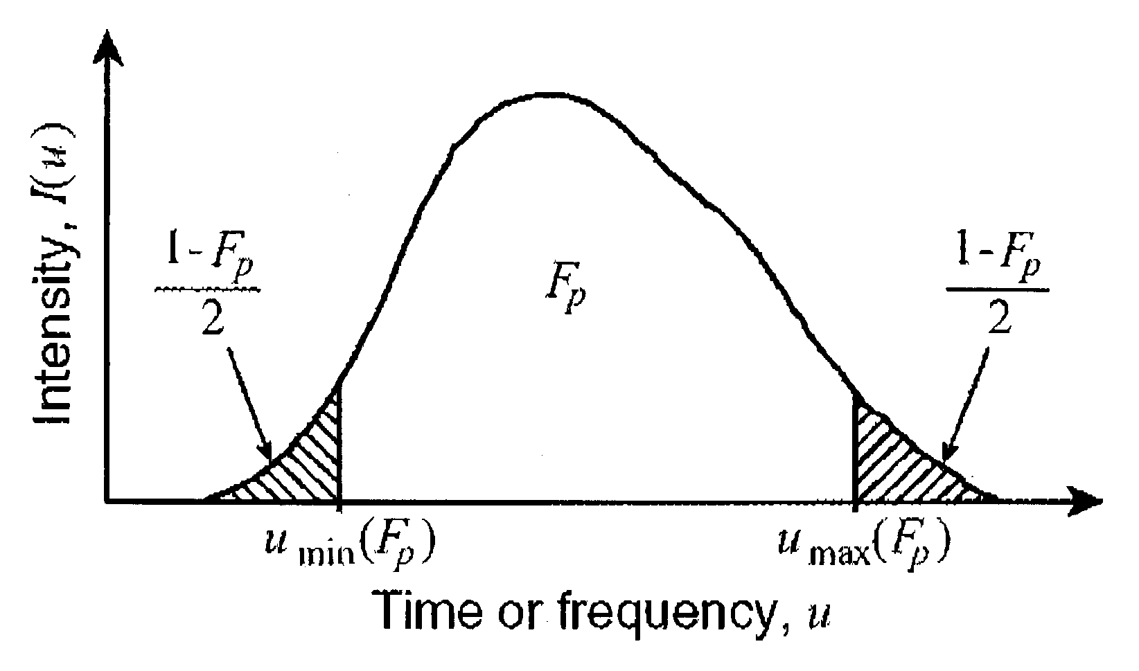
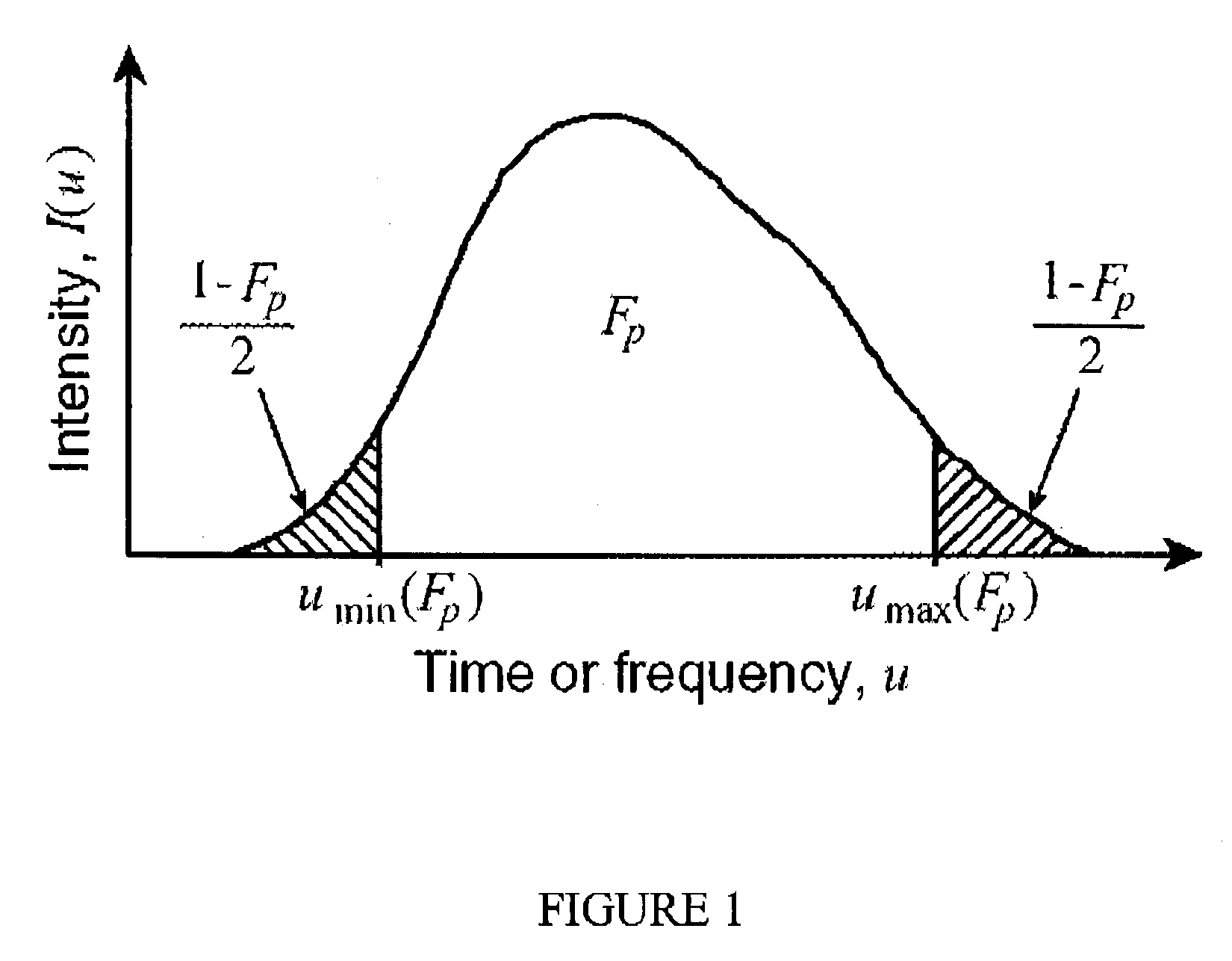
where σv=√{square root over ((v2)−(v)2)}{square root over ((v2)−(v)2)} and σt,min=√{square root over ((t2)−(t)2)}{square root over ((t2)−(t)2)} are the rms-widths. These rms-widths are related to the first- and second-order mom...


PUM


Abstract

There is described a method of characterizing a short laser pulse, the method comprising the steps of obtaining root-mean-square widths of the pulse through second order moments of the pulse; obtaining a spectral width of the pulse using the root-mean-square widths; obtaining a root-mean square temporal width of the pulse; and defining a Pulse Quality Factor proportional to a product of the spectral width and the temporal width. This approach does not require complete characterization of laser pulses and eliminates the need of any assumption to interpret autocorrelation traces. The method can be applied to pulses of arbitrary shape.

Description

FIELD OF THE INVENTION[0001]The invention relates to characterizing laser pulses. More specifically, it relates to characterizing short laser pulses without subjective interpretations of autocorrelation traces and irrespective of the pulse shape.BACKGROUND OF THE INVENTION[0002]Mode-locked lasers are now capable of generating pulses whose duration can be as short as a few femtoseconds (one femtosecond=10−15 sec.). There is a broad variety of mode-locked lasers emitting pulses from nanosecond (one nanosecond=10−9 sec.) to femtosecond duration. Short laser pulses can be amplified in laser amplifiers; they can also be temporally compressed externally to laser systems using the combination of spectral broadening in a nonlinear medium, and propagation in a dispersive material. The peak power of the pulses emitted by ultra-fast laser systems can be as low as one watt in mode-locked semiconductor diodes, and can reach the petawatt range (one petawatt=1015 watts) in the highest power system...

Claims


Application Information

Patent Timeline
Patent Type & Authority Patents(United States)
IPC IPC(8): H01S3/10G01J1/42G01J11/00
CPCG01J11/00G01J1/42
Inventor PICHE, MICHELROUSSEAU, GUY
Owner UNIV LAVAL
Why Eureka
Try Eureka