
Apparatus and method for regulating an SLIC supply voltage

a technology of slic supply voltage and apparatus, which is applied in the direction of electrical apparatus, substation equipment, interconnection arrangements, etc., can solve the problems of increasing power loss p/sub>loss unable to provide sufficient power in the slic circuit to supply the terminal, and unable to achieve the effect of slic circuit power loss reduction

Inactive Publication Date: 2006-08-15
INTEL CORP
View PDF10 Cites 7 Cited by
  • Summary
  • Abstract
  • Description
  • Claims
  • Application Information

AI Technical Summary

Benefits of technology

[0021]The object of the present invention is therefore to provide a method and an apparatus for regulating the supply voltage of an SLIC circuit, in which the power loss produced in the SLIC circuit is minimal.

Problems solved by technology

The power loss Ploss produced in the SLIC circuit produces heat which must be dissipated to the environment.
As the battery voltage Vbattery rises, the power loss Ploss in the SLIC circuit increases.
If, conversely, the battery voltage Vbattery is too low, it is impossible for the SLIC circuit to provide sufficient power to supply the terminal.
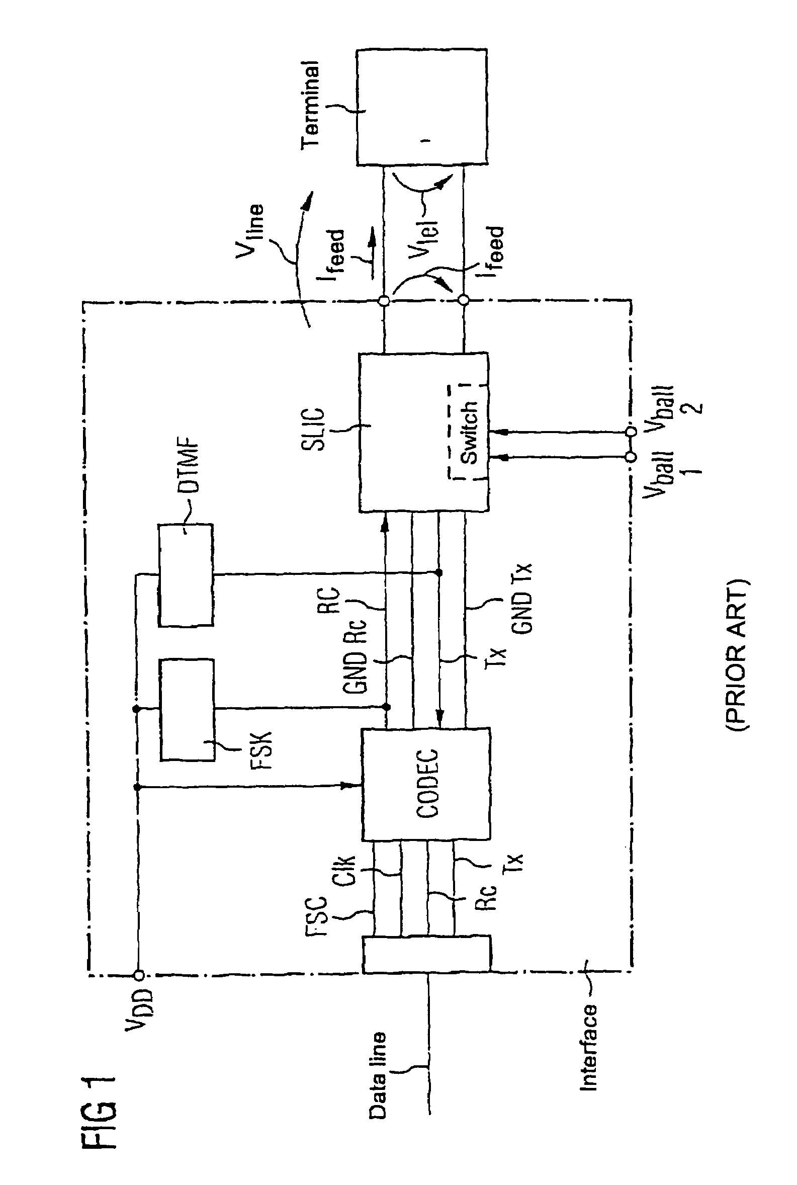
In the conventional interface according to the prior art, as is illustrated in FIG. 1, a switching device is therefore provided in the SLIC circuit, and switches between two or more battery voltages Vbatt depending on the telephone connecting line length L. One disadvantage of switching between different battery voltages Vbatt is that the circuitry complexity for generation of different battery voltages Vbatt is relatively high, and this results in only a minor reduction in the power loss Ploss within the SLIC circuit.

Method used


Image

  • Apparatus and method for regulating an SLIC supply voltage
  • Apparatus and method for regulating an SLIC supply voltage
  • Apparatus and method for regulating an SLIC supply voltage

Examples


Embodiment Construction

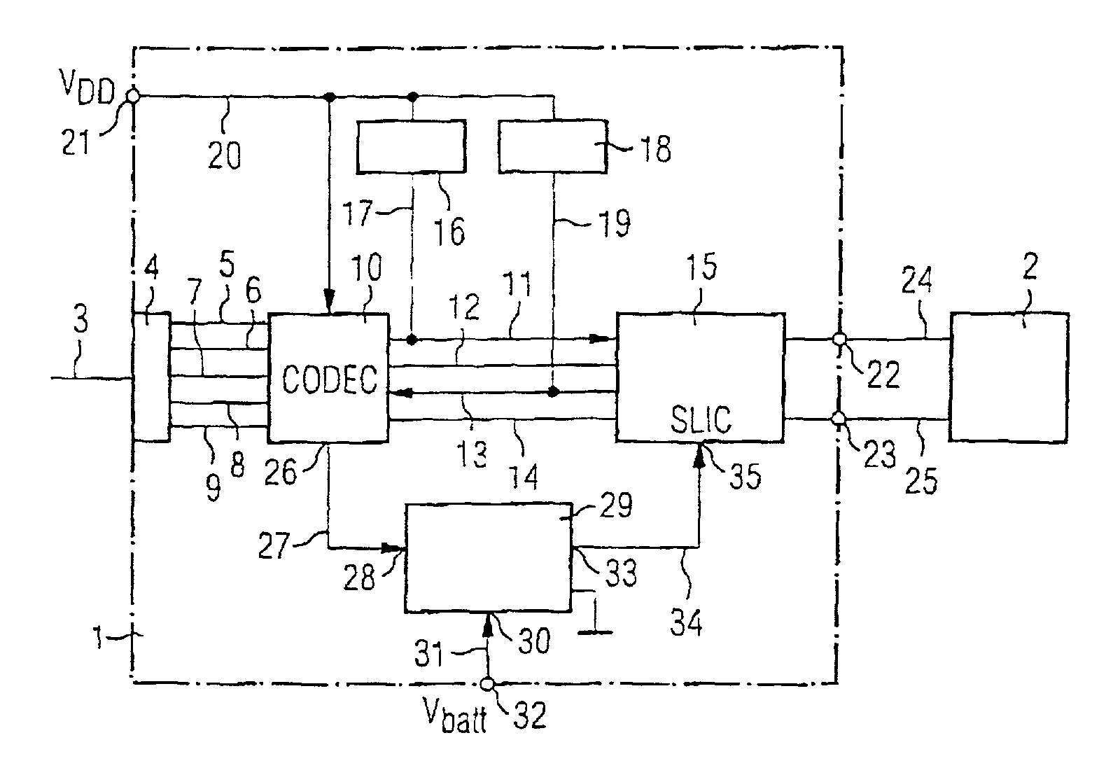
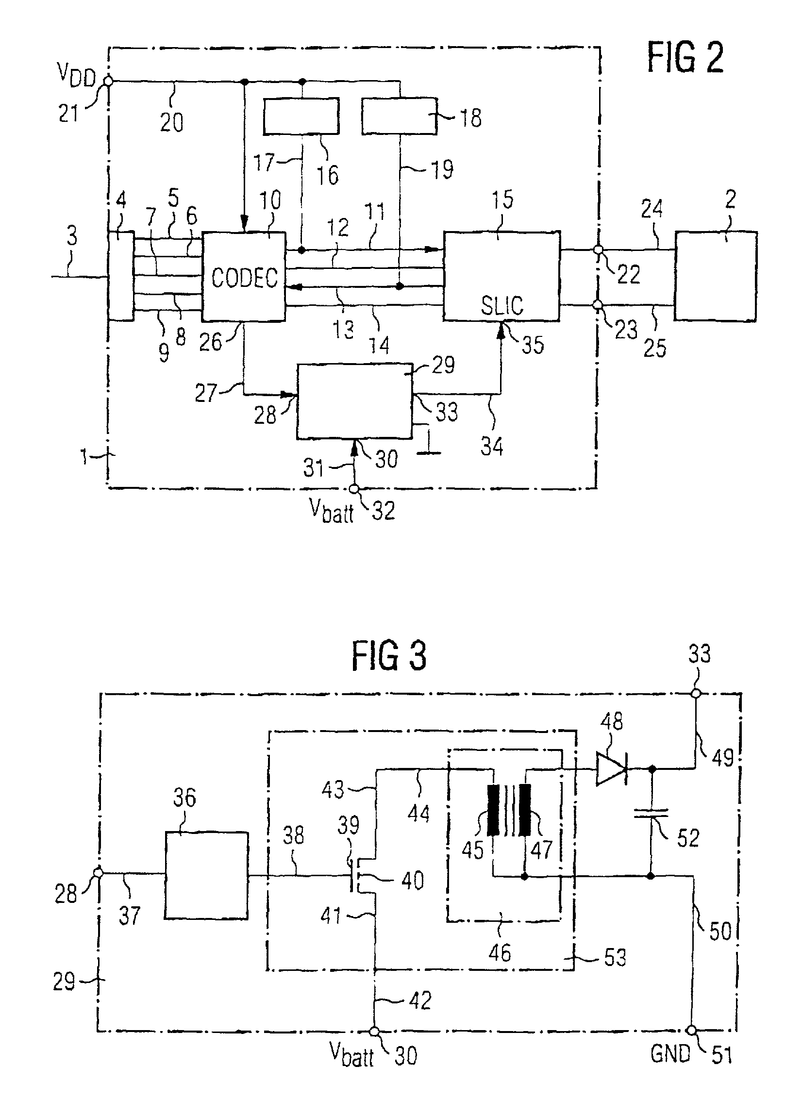
[0055]FIG. 2 shows a block diagram of an interface circuit 1 for connection of an analog terminal 2 to at least one data line 3 for transmission of digital signals. The interface circuit 1 contains a connection 4 for connection of the interface circuit 1 to the data transmission line 3. Voice signal information and data information are transmitted in digital form via the data transmission line 3. The connection 4 is connected via a data frame synchronization line 5 (Frame Sync), a clock line 6, a data receiving line 7, a data transmitting line 8 and a reference ground line 9 to a Codec circuit 10. The digital data applied is decoded by the Codec circuit 10, and is converted to analog signals. The Codec circuit 10 is connected via a receiving line 11, a receiving ground line 12, a transmitting line 13 and a transmitting ground line 14 to an SLIC circuit 15 which is provided in the interface circuit 1.

[0056]An FSK circuit 16 (FSK: Frequency Shift Keying) is connected via a line 17 to ...


PUM


Abstract

Control circuit and method for regulating the supply voltage of an SLIC circuit (15), having a monitoring circuit (36) for calculating an SLIC supply voltage which is required to reach a nominal supply current (Inom) for an analogue terminal (2) which is connected to the SLIC circuit (15); and having a DC / DC converter (53), which is controlled by the monitoring circuit (36), for converting a battery voltage (Vbatt) to the calculated SLIC supply voltage.

Description

RELATED ART[0001]FIG. 1 shows an interface for connecting an analog terminal, in particular an analog telephone, to a digital switching system according to the prior art.[0002]The analog terminal is connected via two telephone lines to an SLIC circuit which is integrated in the interface. The SLIC circuit (SLIC: Subscriber Line Interface Circuit) carries out what are referred to as the BORSCHT tasks, namely:[0003]Battery feeding, that is to say remote power supply feed to the terminal,[0004]Overvoltage protection,[0005]Ringing, that is to say calling the subscriber terminal,[0006]Signaling,[0007]Coding, that is to say PCM coding / decoding, and[0008]Hybrid testing, or testing and measurement.[0009]The SLIC circuit contains battery switching devices for applying various battery voltages Vbatt1, Vbatt2, . . . . The SLIC circuit is connected via a signal receiving line RC and a signal transmitting line TX as well as respectively associated ground lines to a Codec circuit. The SLIC circui...

Claims


Application Information

Patent Timeline
Patent Type & Authority Patents(United States)
IPC IPC(8): H04M1/00H04M9/00H04M19/00H04Q11/04
CPCH04M19/005H04Q11/0421H04Q2213/13003H04Q2213/13034H04Q2213/1308H04Q2213/13405H04Q2213/13106H04Q2213/13166H04Q2213/13302H04Q2213/13305H04Q2213/1332H04Q2213/13082
Inventor PRUECKLMAYER, STEPHANSCHOENBERGER, MICHAEL
Owner INTEL CORP
Learn More