Threshold voltage (Vth), power supply (VDD), and temperature compensation bias circuit for CMOS passive mixer

a bias circuit and temperature compensation technology, applied in the field of radio frequency mixers, can solve the problems of unattractive use as mixers, unfavorable conversion gain, noise figure, etc., and achieve the effect of stabilizing conversion gain, linearity and noise figur

Active Publication Date: 2006-08-15
WIPRO LTD +1
View PDF14 Cites 30 Cited by
  • Summary
  • Abstract
  • Description
  • Claims
  • Application Information

AI Technical Summary

Benefits of technology

[0016]It is an object of at least one embodiment of the present invention to provide circuits and a method to stabilize the conversion gain, linearity and noise figure of a passive mixer.
[0019]It is still another object of the present invention to make the variation of the conversion gain very small and thus to maintain excellent linearity performance.

Problems solved by technology

Additionally, the 10% power-supply variation and the circuit operating temperature from −35° C. to 85° C. worsen the stability of the various performance parameters such as conversion gain, noise figure, and linearity.
Active mixers have another set of problems which makes them equally unattractive for use as mixers.

Method used


Image

  • Threshold voltage (Vth), power supply (VDD), and temperature compensation bias circuit for CMOS passive mixer
  • Threshold voltage (Vth), power supply (VDD), and temperature compensation bias circuit for CMOS passive mixer
  • Threshold voltage (Vth), power supply (VDD), and temperature compensation bias circuit for CMOS passive mixer

Examples


Embodiment Construction

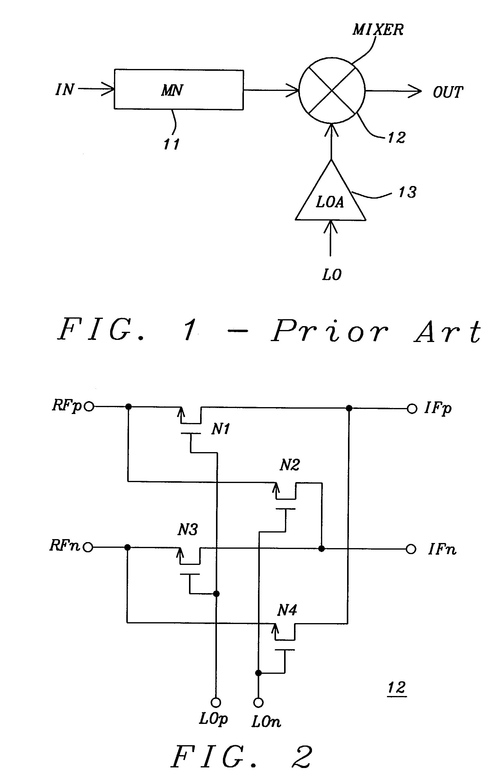
[0030]FIG. 2 shows the schematic diagram of a CMOS passive mixer core 12. It comprises four n-channel MOSFET transistors, connected as shown, and allows input frequency up- or down-conversion to an output frequency for any local oscillator (LO) frequency. The radio frequency (RF) inputs are fed differentially from ports RFp and RFn, LO inputs are fed differentially from ports LOp and LOn, and the intermediate frequency (IF) outputs are obtained at ports IFp and IFn. The source and drain of first transistor N1 are coupled between input RFp and output IFp, respectively. The source and drain of second transistor N2 are coupled between input RFp and output IFn, respectively. The source and drain of third transistor N3 are coupled between input RFn and output IFn, respectively, and the source and drain of fourth transistor N4 are coupled between input RFp and output IFn, respectively. The gates of N1 and N3 are coupled to LOp, and gates of N2 and N4 are coupled to LOn.

[0031]To stabilize ...


PUM


Abstract

A biasing circuit for a CMOS passive mixer core to stabilize its conversion gain, linearity and noise figure. The RF inputs are fed differentially from the two RF ports, the LO inputs are fed differentially from the two LO ports, and the IF outputs are obtained at the two IF ports. The biasing circuit comprises a reference current derived from the bandgap voltage and a n-channel MOSFET transistor. The conversion gain is stabilized by keeping the Vgs−Vth value of the passive mixer core almost constant at all process corners, temperature and power supply changes. This is achieved by implementing Vs in such a way that it will increase the same amount as VDD decreases, and that Vs will decrease the same amount as Vth increases.

Description

FIELD OF THE INVENTION[0001]The invention relates to radio frequency (RF) mixers, and more particularly to a compensation bias circuit for use with CMOS passive mixers.DESCRIPTION OF THE RELATED ART[0002]FIG. 1 shows the block diagram of a passive mixer of the prior art, where 11 (MN) is the matching network for the mixer with input IN, 12 (MIXER) is the passive mixer core, and 13 (LOA) is the local oscillator (LO) amplifier (buffer). The MIXER has an output OUT. Connections in FIG. 1, though shown as single lines, are paired lines. The conversion gain, noise figure, and linearity performance of a CMOS passive mixer will be varied by the Vth of transistors, the circuit operating temperature, and power supply variation to the circuit. In a standard CMOS process, threshold voltage of a deep sub-micron transistor can vary as much as ±20%, at different process corners. Additionally, the 10% power-supply variation and the circuit operating temperature from −35° C. to 85° C. worsen the st...

Claims


Application Information

Patent Timeline
Patent Type & Authority Patents(United States)
IPC IPC(8): H04B1/28H04B1/16H03D7/14
CPCH03D7/1441H03D7/1458H03D7/1466H03D2200/0033H01L2924/0002H03D2200/0043H01L2924/00
Inventor TAN, CHUN GEIKITOH, MASAAKI
Owner WIPRO LTD
Why Eureka
Try Eureka