Fuel-air premixing system for a catalytic combustor

a technology of catalytic combustor and fuel air, which is applied in the ignition of turbine/propulsion engine, physical/chemical process catalysts, separation processes, etc., can solve the problems of no/sub>x/sub>produced in the peak temperature zone of the combustor, the breakdown of the central vortex, and the turbine generated torqu

Inactive Publication Date: 2006-08-22
KAWASAKI HEAVY IND LTD
View PDF46 Cites 122 Cited by
  • Summary
  • Abstract
  • Description
  • Claims
  • Application Information

AI Technical Summary

Problems solved by technology

The high temperature combustion of the fuel-air mixture expands across a rotating turbine, resulting in a torque created by the turbine.
These high temperatures also become the source of nitrogen oxide and nitrogen dioxide (NOx) emissions, a known pollutant.
Unfortunately, virtually all of the NOx produced in the peak temperature zones within the combustor is exhausted into the atmospher...

Method used


Image

  • Fuel-air premixing system for a catalytic combustor
  • Fuel-air premixing system for a catalytic combustor
  • Fuel-air premixing system for a catalytic combustor

Examples


Embodiment Construction

[0035]The present invention provides fuel-air premixers for catalytic combustors. The following description is presented to enable any person skilled in the art to make and use the invention. Descriptions of specific applications are provided only as examples. Various modifications to the preferred embodiments will be readily apparent to those skilled in the art, and the general principles defined herein may be applied to other embodiments and applications without departing from the spirit and scope of the invention. Thus, the present invention is not intended to be limited to the examples shown, but is to be accorded the widest scope consistent with the principles and features disclosed herein.

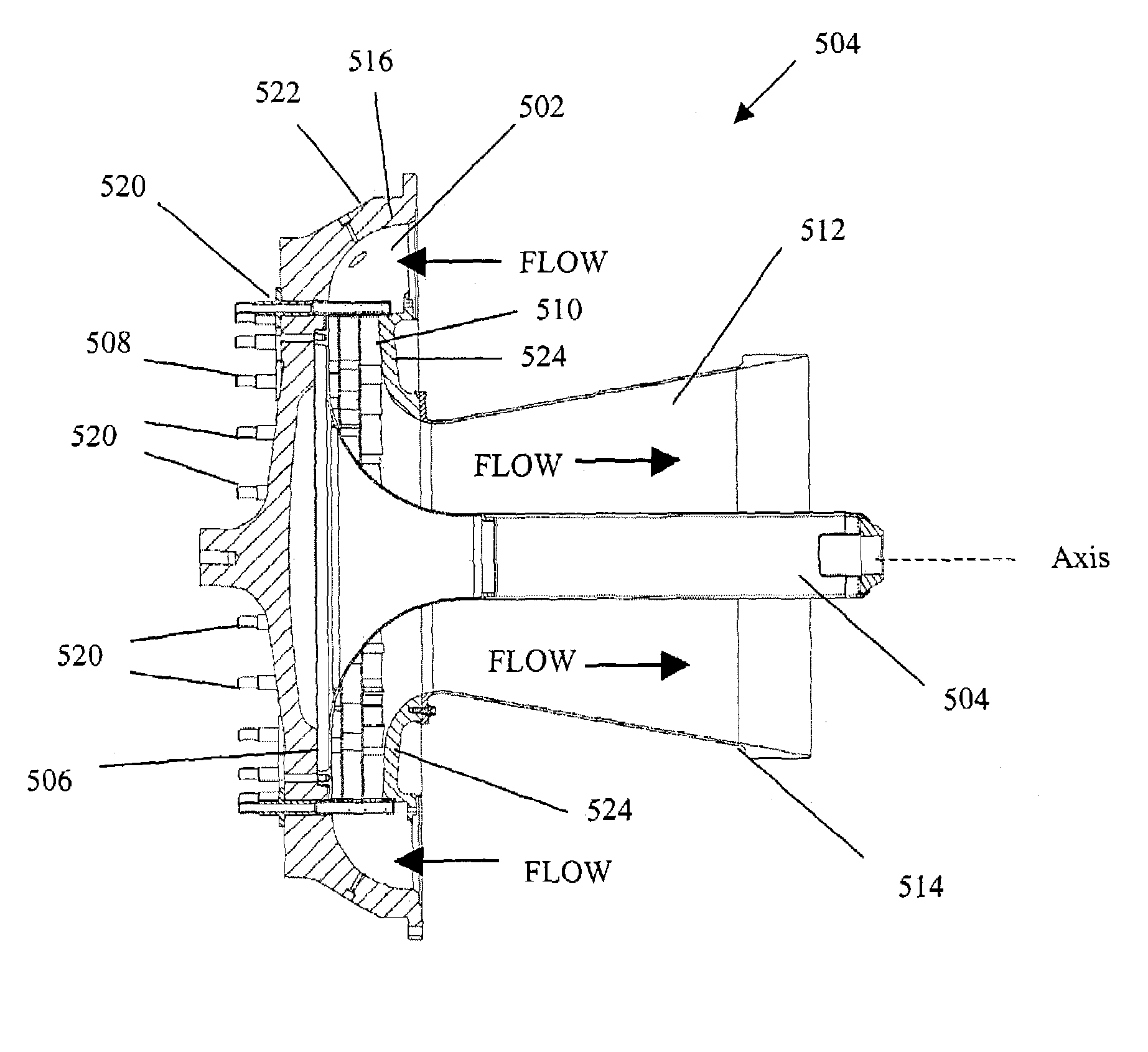
[0036]According to one aspect of the invention a premixer is described that includes a fuel inlet system and a swirler located within a mixer housing. The fuel inlet system is located upstream of the swirler. The swirler includes an assembly of one or more baffles that impart a swirling motio...


PUM

PropertyMeasurementUnit
Fractionaaaaaaaaaa
Angleaaaaaaaaaa
Angleaaaaaaaaaa

Abstract

Disclosed is a unique fuel and air premixing system for a gas turbine catalytic combustion system. The mixer utilizes a multi-channel counter-rotating swirler with aerodynamically shaped fuel pegs located upstream of the swirler. The premixing system provides the downstream catalyst with a fuel-air mixture sufficiently uniform for proper catalyst operation and wide operating limits. Features have been incorporated in the system to make it resistant to flameholding.

Description

CROSS-REFERENCE TO RELATED APPLICATIONS[0001]The present application claims benefit of earlier filed provisional application U.S. Ser. No. 60 / 384,497, entitled “FUEL-AIR PREMIXING SYSTEM FOR A CATALYTIC COMBUSTOR,” filed on May 31, 2002, which is incorporated herein in its entirety by reference.BACKGROUND[0002]1. Field of the Invention[0003]This invention relates generally to a catalytic combustor for a gas turbine engine, and in particular, to a fuel-air mixer for a catalytic combustor for a gas turbine engine.[0004]2. Description of Related Art[0005]One widely used device for the generation of electricity, power, and heat is the gas turbine engine. A typical gas turbine engine operates by intaking air and pressurizing it using a rotating compressor. The pressurized air is passed through a chamber, or “combustor,” wherein fuel is mixed with the air and burned. The high temperature combustion of the fuel-air mixture expands across a rotating turbine, resulting in a torque created by...

Claims


Application Information

Patent Timeline
IPC IPC(8): F02C1/00F23R3/28F23R3/40
CPCF23R3/40F23R3/286F23C2900/07001
Inventor CORR, II, ROBERT ANTHONYCARON, TIMBARNES, JOHN
Owner KAWASAKI HEAVY IND LTD
Why Eureka
Try Eureka