Apparatus for increasing induction air flow rate to a turbocharger

a turbocharger and air flow technology, applied in the field of air induction systems, can solve the problems of not always being able to achieve the lowest possible entry loss of the turbocharger, the prior art does not combine three features to achieve the effect of reducing the head loss of the system, facilitating the flow of air, and minimizing the overall restriction

Inactive Publication Date: 2006-08-22
VISTEON GLOBAL TECH INC
View PDF61 Cites 33 Cited by
  • Summary
  • Abstract
  • Description
  • Claims
  • Application Information

AI Technical Summary

Benefits of technology

[0008]The present invention alleviates one or more of the shortcomings described above by providing a method and system that enable enhanced air flow to the air intake of an internal combustion engine having a turbocharger. The present invention allows for the reduction of system head loss by minimizing overall restriction within the air induction system.
[0009]In one aspect of the present invention, an air induction system includes a clean air duct directing airflow to the inlet of a turbocharger. The clean air duct includes a plenum or expansion volume for reducing flow velocity and minimizing restriction. The plenum is located within the area directly in front of the turbocharger inlet. The clean air duct may further include a diffuser upstream of the plenum, as well as a bell-mouth transition positioned between the plenum and the inlet to the turbocharger. The diffuser and bell-mouth transition are also configured to reduce overall system restriction and head loss.
[0010]In another aspect of the present invention, an air induction system includes a clean air duct directing airflow to the inlet of a turbocharger that includes a means for reducing the velocity of the air flow within an area directly in front of the inlet to the turbocharger.

Problems solved by technology

Prior turbocharged induction systems exhibit problems related to the loss of air induction system pressure head.
However, these solutions are not always possible due to the placement of the engine relative to the surrounding vehicle packaging.
Although the use of a single approach, such as either a diffuser, an expansion chamber, or a bell-mouth transition, to reduce static pressure losses is well-known, these three features have not been combined in the prior art to obtain the lowest possible turbocharger entrance losses.
Moreover, the prior art air induction systems do not utilize a plenum, diffuser, or other means for restoring static pressure head within the area directly in front of the inlet of the turbocharger.
Additionally, packaging and manufacturing constraints have often led to design inefficiencies.
However, such bends or elbows create a high restriction yielding lower than desired pressure conditions at the inlet of the turbocharger compressor.
Furthermore, the prior art air induction systems did not utilize the limited space available after the engine and underhood compartment had already been designed to enhance the flow of induction air.

Method used


Image

  • Apparatus for increasing induction air flow rate to a turbocharger
  • Apparatus for increasing induction air flow rate to a turbocharger
  • Apparatus for increasing induction air flow rate to a turbocharger

Examples


Embodiment Construction

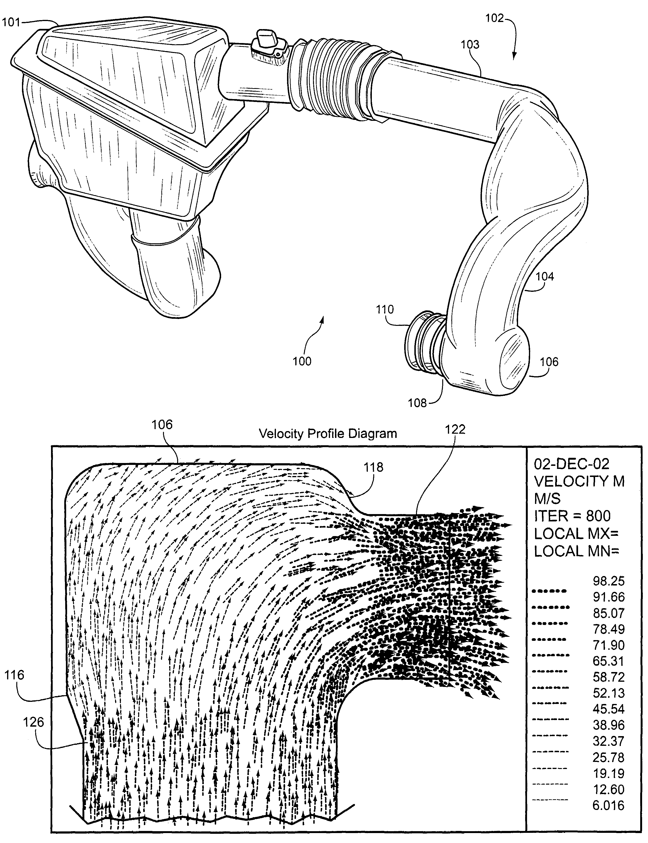
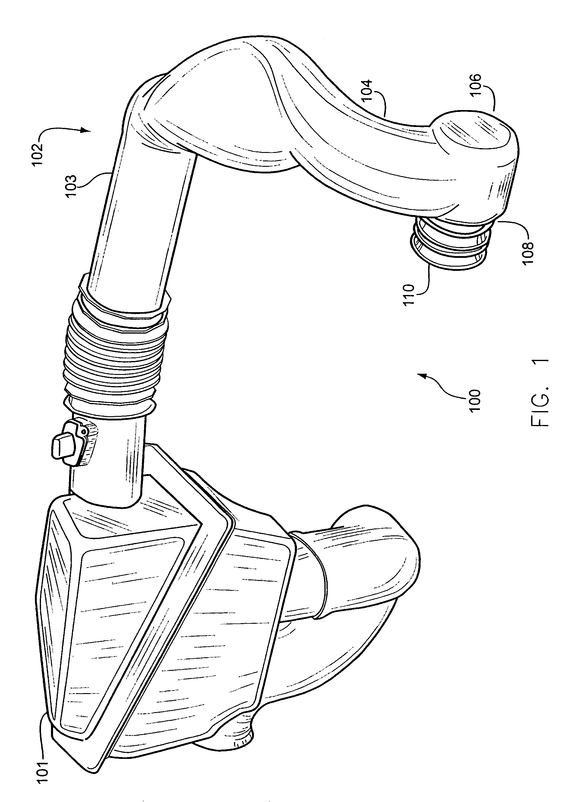
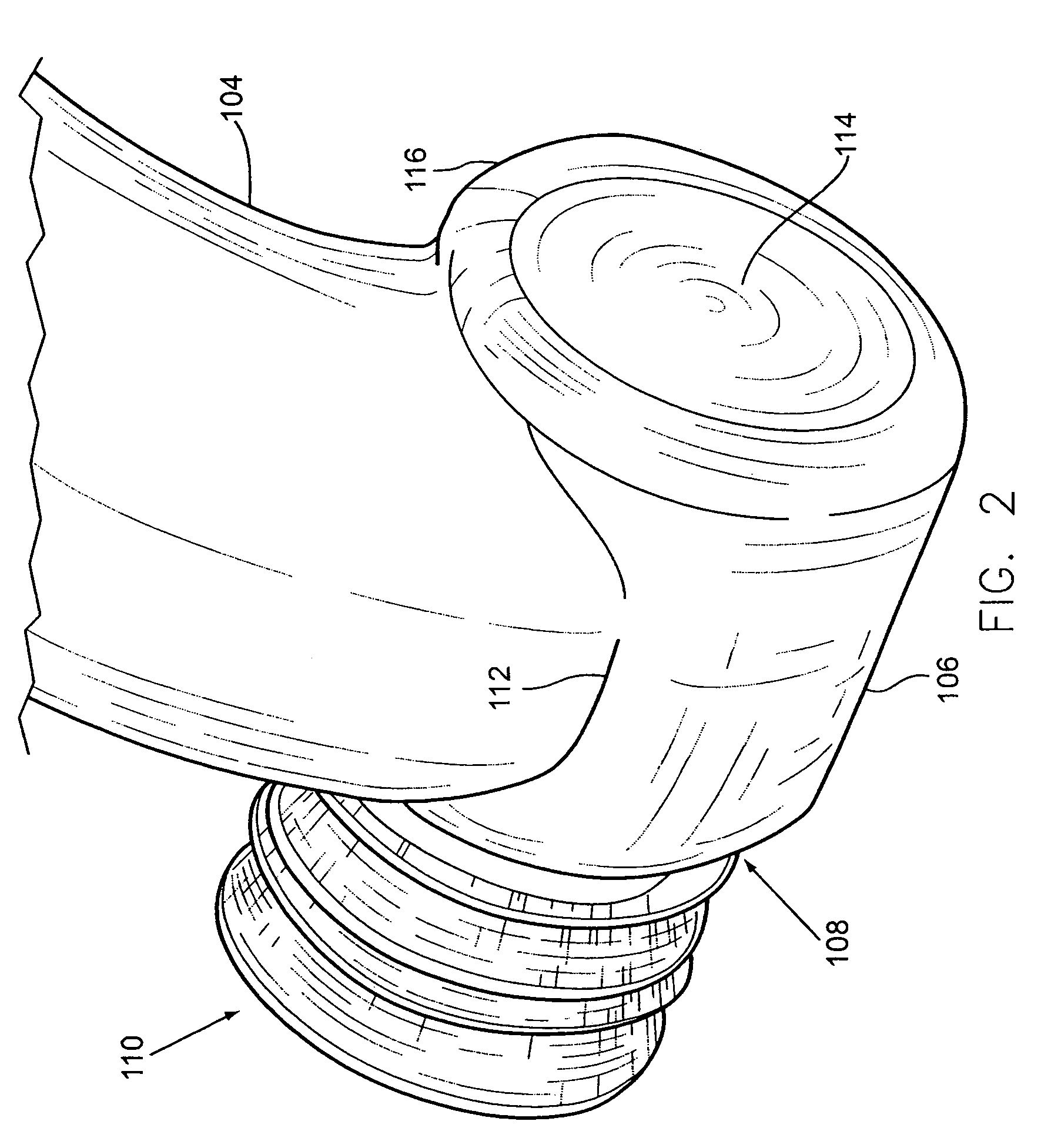
[0019]In accordance with the present invention, a method and system are provided that enable enhanced air flow to the air intake of an internal combustion engine having a turbocharger. In the air induction system provided, various components are integrated into a clean air duct in such a manner as to minimize system head loss.

[0020]FIGS. 1 and 2 illustrate perspective views of one embodiment of the air induction system in accordance with the present invention. As shown in FIG. 1, the air induction system 100 for use in an internal combustion engine having a turbocharger includes a clean air duct 102. The clean air duct 102 is operable to deliver induction air flow to the turbocharger inlet 110 from an air filter or cleaner (located within a filter housing 101), which in turn draws air from an air intake (typically located within the engine bay of the motor vehicle (not shown)). The clean air duct 102 illustrated integrates a diffuser 104, a plenum 106, a bell-mouth transition 108, a...


PUM


Abstract

A system that enables enhanced air flow to the air intake of an internal combustion engine having a turbocharger is disclosed. The air induction system includes a plenum or expansion chamber located within the area directly in front of the inlet of the turbocharger. Alternatively, the air induction system may include a diffuser and / or an expansion chamber for reducing the velocity of the air flow within the clean air duct in an area directly in front of the inlet of the turbocharger.

Description

FIELD OF THE INVENTION[0001]The present invention relates generally to air induction systems. More particularly, the invention relates to a compact air induction system for increasing induction air flow rate to a turbocharger.BACKGROUND OF THE INVENTION[0002]An internal combustion engine typically includes an air induction system with which air is introduced into an intake manifold assembly. In contrast, the air induction system of a turbocharged engine delivers induction air to the impeller of the turbocharger compressor instead of directly to the intake manifold assembly of the engine.[0003]Prior turbocharged induction systems exhibit problems related to the loss of air induction system pressure head. Common attempts to minimize air induction system head loss include the use of short-length air induction systems, large diameter ducting, or ducting with as few directional changes as possible. However, these solutions are not always possible due to the placement of the engine relati...

Claims


Application Information

Patent Timeline
Patent Type & Authority Patents(United States)
IPC IPC(8): F02B33/00B62D61/02F01D1/02F02B33/44F02M37/00F02B37/00F02M35/10
CPCF02B37/00F02M35/10157F02M35/10013Y02T10/144Y02T10/12
Inventor SORERSEN, JOHN CHRISTIANKEMPF, JAMES JOHNGRIMES, RYAN E.
Owner VISTEON GLOBAL TECH INC
Why Eureka
Try Eureka