All-terrain vehicle
- Summary
- Abstract
- Description
- Claims
- Application Information
AI Technical Summary
Benefits of technology
Problems solved by technology
Method used
Image
Examples
first embodiment
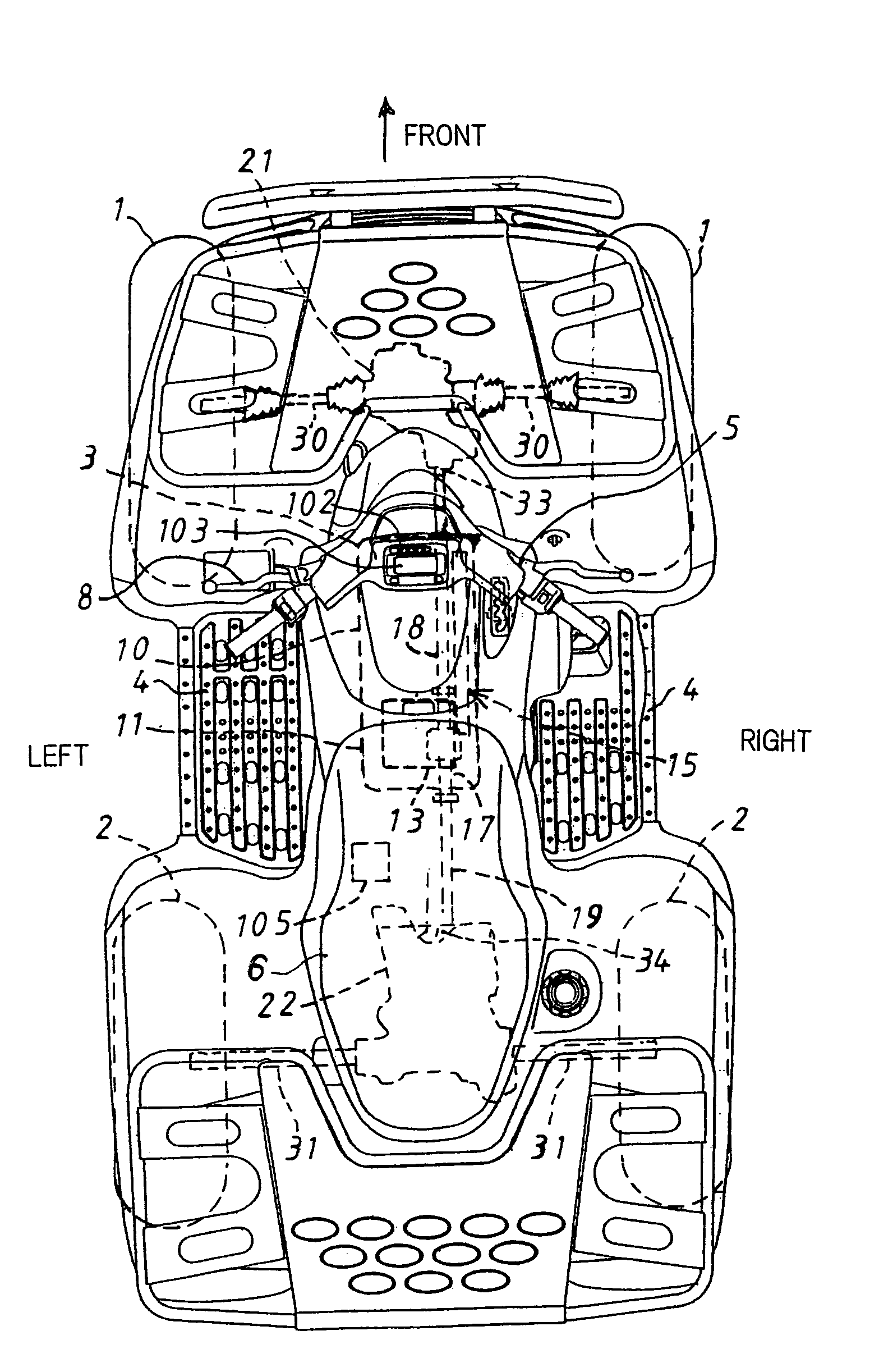
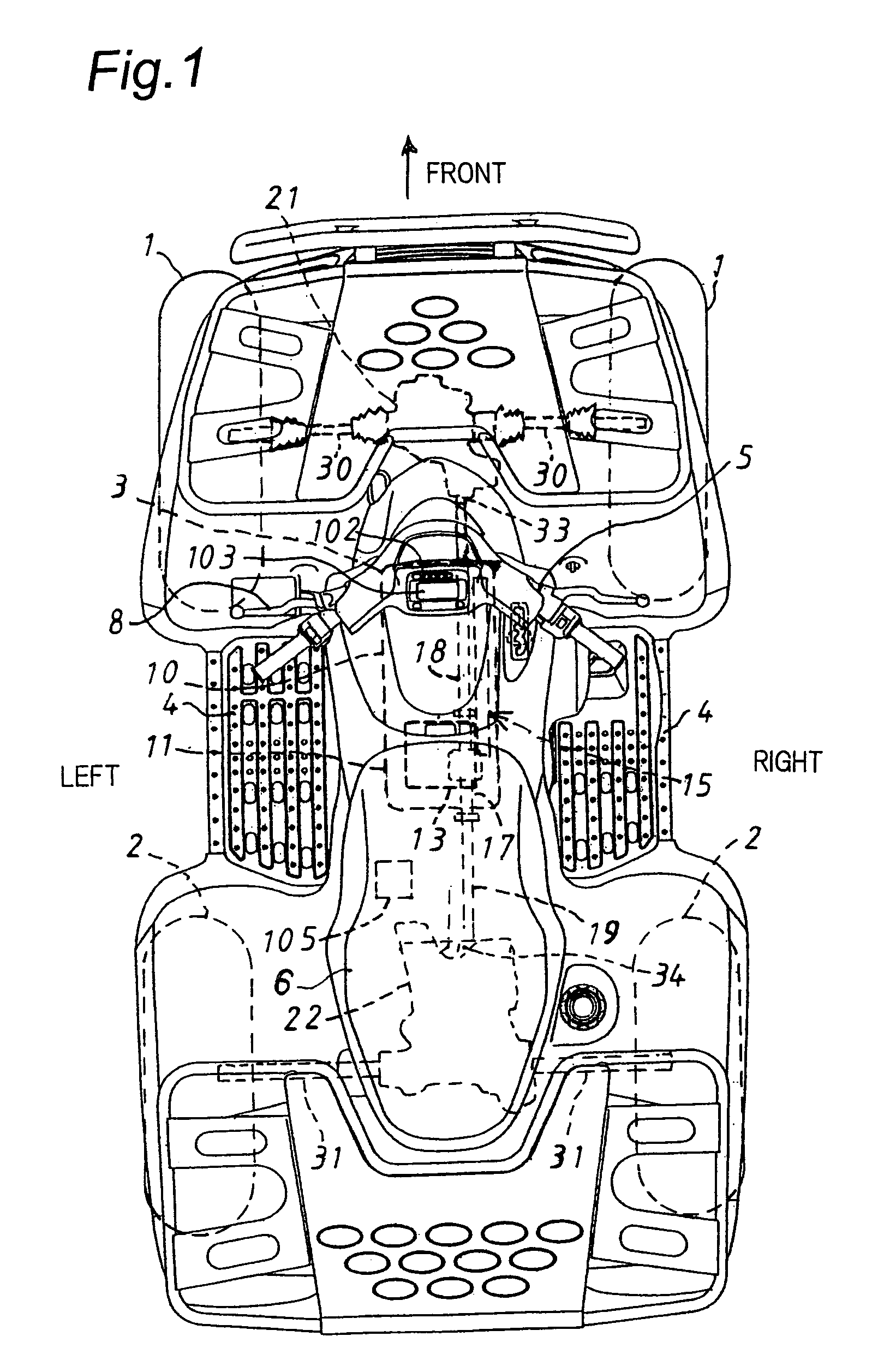
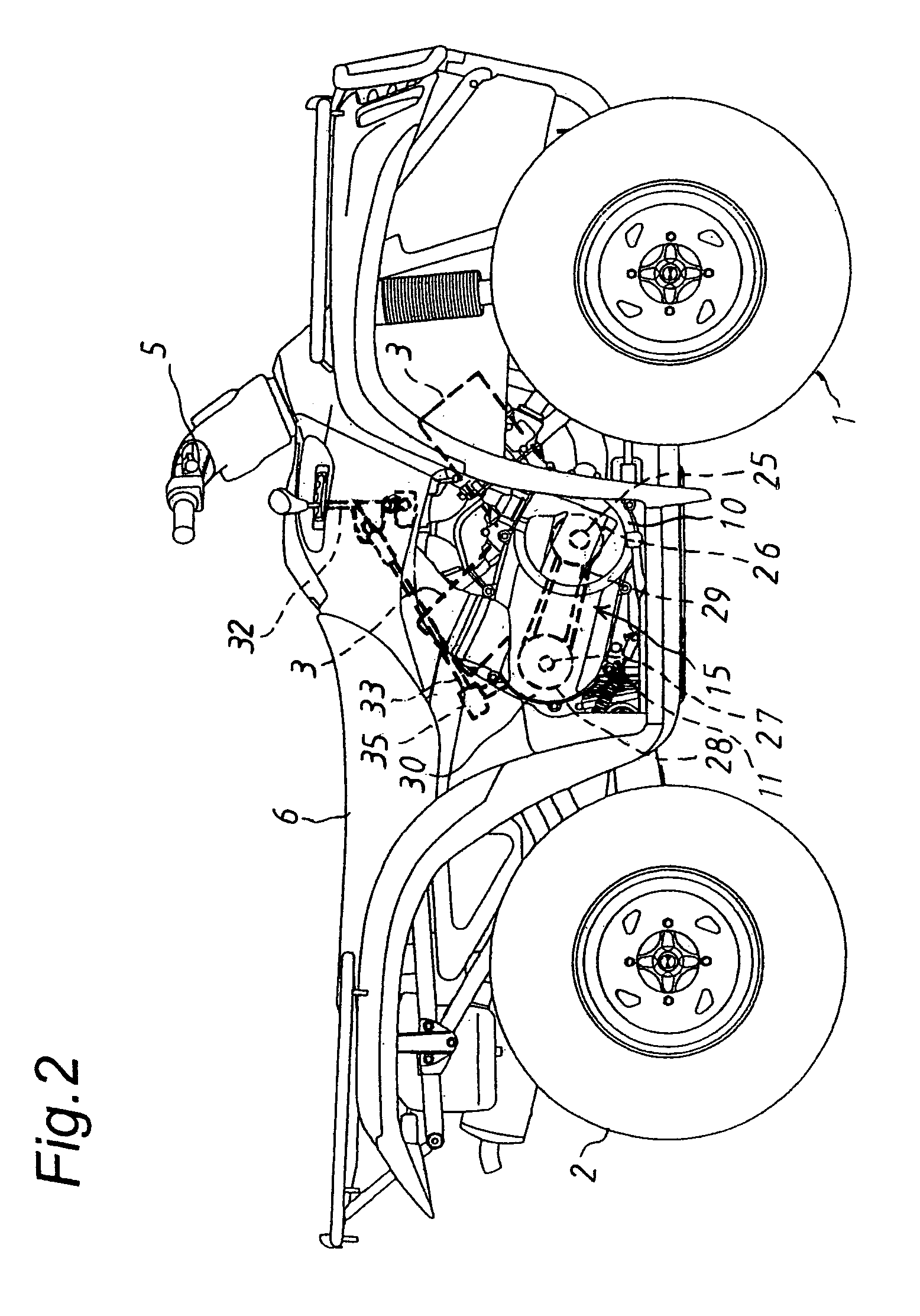
[0037]First, with reference to FIGS. 1 through 7, the description is made of a vehicle according to the present invention.
[0038]FIG. 1 is a plan view showing the vehicle. In the explanation below, a “right and left direction” is defined as such a direction that a driver is taken as a reference with respect to a body of the vehicle and with respect to a direction in which the vehicle moves forward.
[0039]The vehicle has right and left front wheels (also, hereinbelow referred to as a “front wheel pair”) 1, right and left rear wheels (also, hereinbelow referred to as a “rear wheel pair”) 2, an engine 3 between the front wheel pair 1 and the rear wheel pair 2, and foot-steps 4 on both sides of the body of the vehicle. Further, as shown in FIG. 1, there is arranged a handlebar 5 for steering the vehicle in a front upper part of the body, and there is arranged a straddle type seat 6 in a rear upper part of the body. The handlebar 5 has a grip part provided with a brake lever 8 and so on.
case 10
[0040]A crank case 10 of the engine 3 extends rearward, and the crank case 10 has a transmission case 11 integrally at a rear part of the crank case 10. There is provided a gear transmission (i.e. gear type sub-transmission) 13 inside the transmission case 11, and there is provided an automatic belt converter (i.e. automatic V-belt transmission) 15 on a right side of the crank case 10, which is located upstream of a transmitting path of a drive power from the engine for the vehicle with respect to the gear transmission 13.
[0041]Under the transmission case 11, a drive shaft 17 extends back and forth. A front part of the drive shaft 17 is connected to a gear mechanism accommodated inside a reduction gear case 21 for the front wheel pair 1, via a propeller shaft 18 for the front wheel pair 1. On the other hand, a rear part of the drive shaft 17 is connected to a gear mechanism accommodated inside a reduction gear case 22 for the rear wheel pair 2, via a propeller shaft 19 for the rear ...
second embodiment
[0104]Next, with reference to FIGS. 8 and 9, a vehicle is described according to the present invention.
[0105]Namely, in the second embodiment, instead of employing the backward movement positional detecting switch 90 as shown in FIGS. 3 and 5, the rotor 115 for detection and the backward movement detecting sensor 111 which opposes a peripheral surface of the rotor 115 for detection are utilized as the backward movement detection mechanism. The rotor 115 is fixed to an edge surface of the output gear 80 which is fixed to the output shaft 63. Similar to the aforementioned vehicle speed sensor 110, the backward movement detecting sensor 111 outputs an electric pulse by detecting a change in magnetic flux which passes through a detection element provided at a tip part of the sensor 111.
[0106]By the way, the output shaft 63 with the output gear 80 rotate in reverse directions, upon forward and backward movements of the vehicle.
[0107]FIG. 8 shows the engine control mechanism, according to...
PUM
 Abstract
Description
Claims
Application Information
 - R&D
- Intellectual Property
- Life Sciences
- Materials
- Tech Scout
- Unparalleled Data Quality
- Higher Quality Content
- 60% Fewer Hallucinations
Browse by: Latest US Patents, China's latest patents, Technical Efficacy Thesaurus, Application Domain, Technology Topic, Popular Technical Reports.
© 2025 PatSnap. All rights reserved.Legal|Privacy policy|Modern Slavery Act Transparency Statement|Sitemap|About US| Contact US: help@patsnap.com


