Laminar-flow airfoil

a laminar-flow airfoil and trailing edge technology, applied in the direction of all-wing aircraft, wing shapes, drag reduction, etc., can solve the problems of large head-lowering pitching moment, drag-divergence phenomenon, difficulty in ensuring mileage, etc., to reduce undesirable head-lowering pitching moment and reduce drag on laminar-flow airfoils.

Active Publication Date: 2006-08-22
AMERICAN HONDA MOTOR COMPANY
View PDF13 Cites 18 Cited by
  • Summary
  • Abstract
  • Description
  • Claims
  • Application Information

AI Technical Summary

Benefits of technology

[0013]Accordingly, it is an object of the present invention to decrease an undesirable head-lower

Problems solved by technology

However, when a portion of a wing surface in the vicinity of a leading edge is rough, the largest lift disadvantageously tends to decrease largely, leading to a great problem during takeoff or landing of the airplane.
These laminar-flow airfoils enables a reduction in the drag, but have a problem of causing a large head-lowering pitching moment.
Moreover, because these laminar-flow airfoils are for use in a low-speed range, they have a problem of causing drag-divergence phenomenon at an early stage, of a subsonic speed range.
However, the largest lift in a lower Reynolds number range is small and the capacity of an inner-wing fuel tank is insufficient because the wing thi

Method used


Image

  • Laminar-flow airfoil
  • Laminar-flow airfoil
  • Laminar-flow airfoil

Examples


Embodiment Construction

[0025]The present invention will now be described by way of a preferred embodiment with reference to the accompanying drawings.

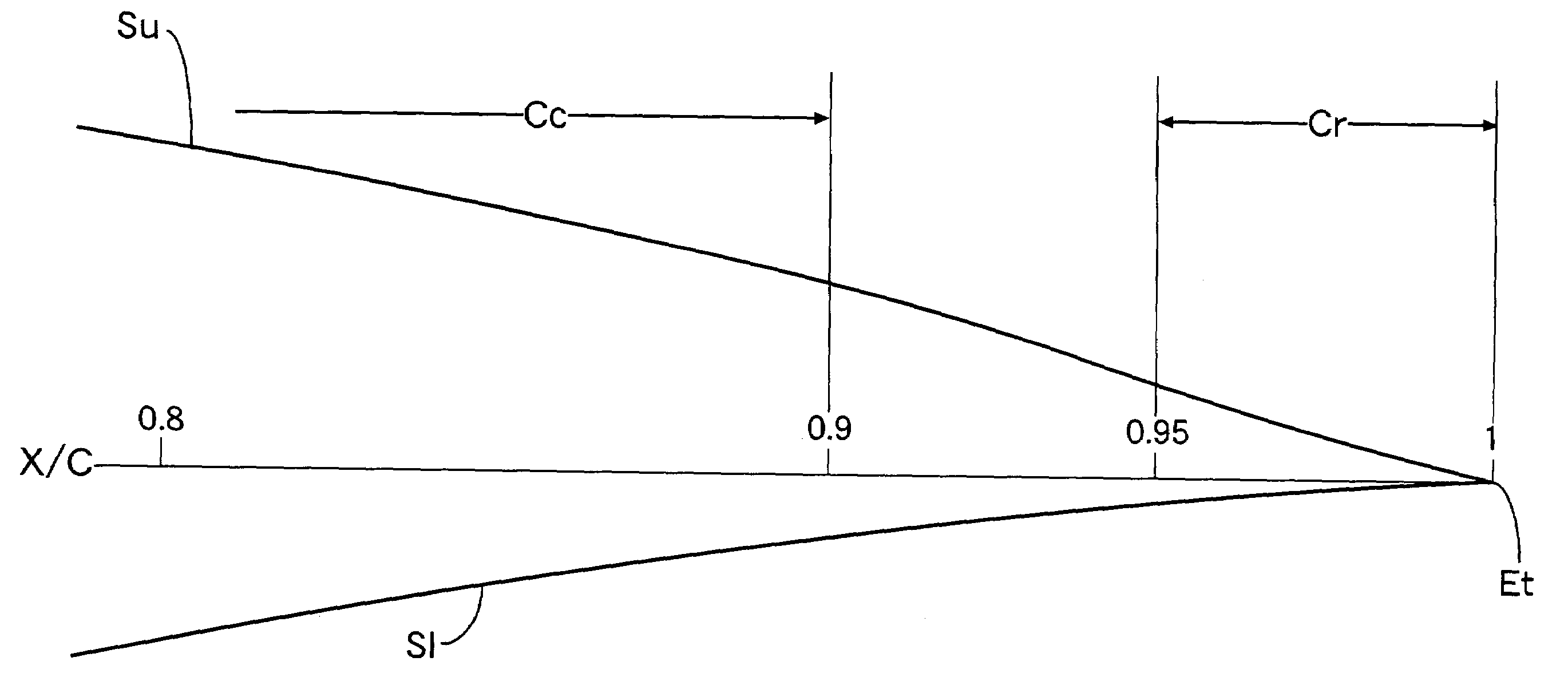
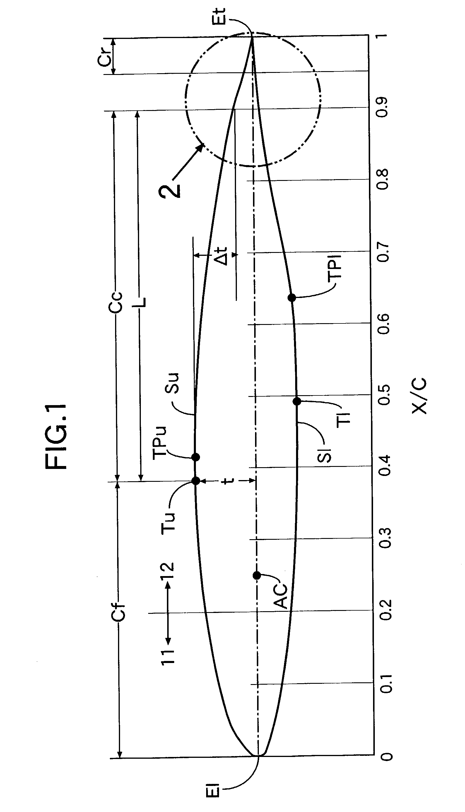
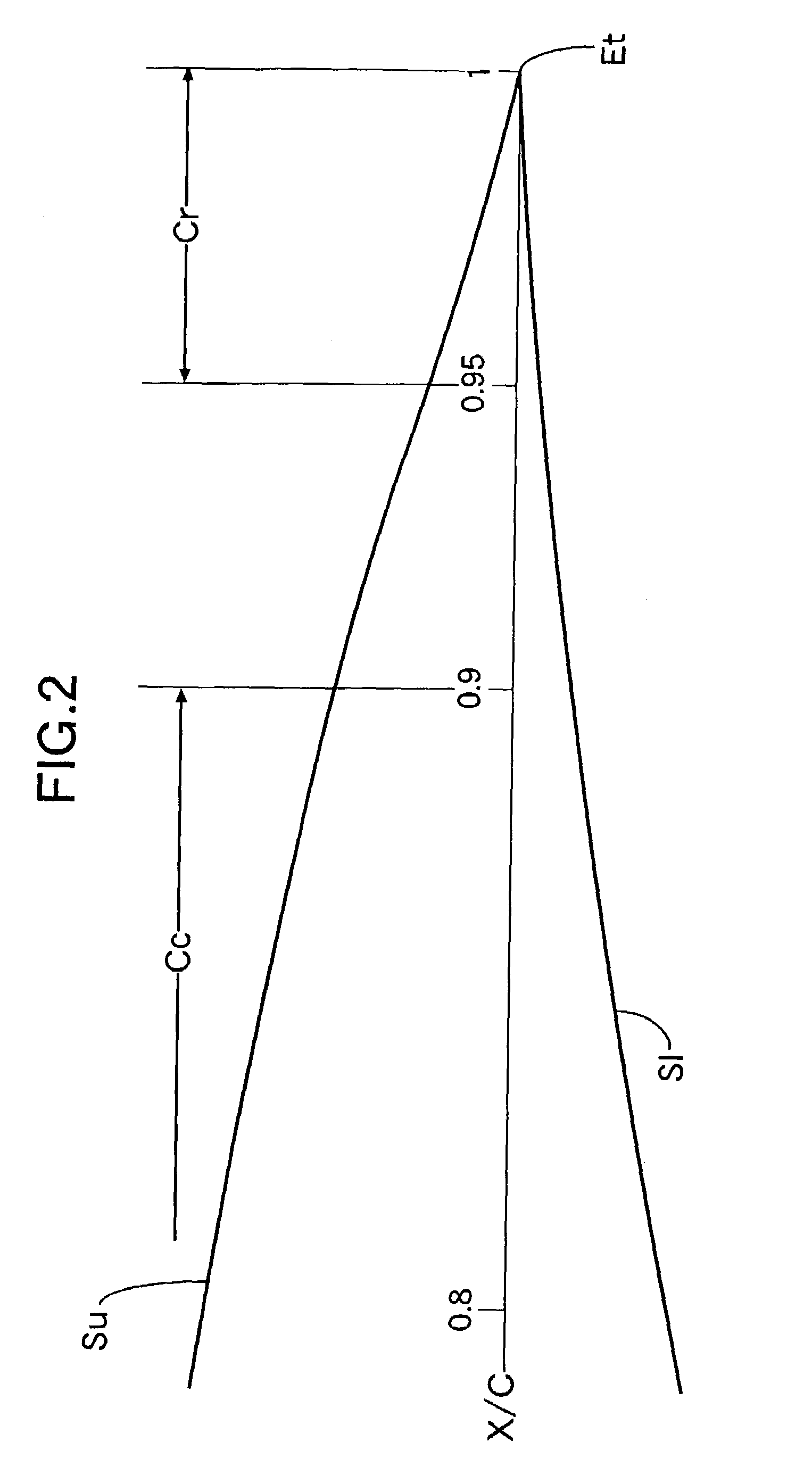
[0026]Referring first to FIG. 1, the profile of a laminar-flow airfoil according to the present embodiment is comprised of an upper wing surface Su, a lower wing surface S1, a leading edge E1 and a trailing edge Et. A largest-thickness position Tu on the upper wing surface SU measured from a cord line lies at a point corresponding to 38% of a wing chord length C in the present embodiment, to form a laminar-flow boundary layer region. A transition point TPu, at which the laminar-flow boundary layer region changes to a turbulent-flow boundary layer region, exists in the vicinity of the largest thickness position Tu. The transition point TPu lies near a position corresponding to 42% of the wing chord length C. A largest-thickness position T1 on the lower wing surface S1 measured from the cord line lies at a point corresponding to 49% of the wing chord length C ...


PUM


Abstract

An upper wing surface of a laminar-flow airfoil for decreasing an undesirable head-lowering pitching moment around an aerodynamic center of the airfoil. The upper wing surface includes: a convex front profile portion extending from a leading edge to a largest-thickness point located corresponding to 38% of a wing chord length. A convex central profile portion extends from the largest-thickness point to a position corresponding to 90% of the wing chord length at which a value obtained by dividing a thicknesswise difference between the position and the largest-thickness point by a distance in a direction of the wing chord from the largest-thickness point is equal to or smaller than 0.12. A concave rear profile portion extends from a position corresponding to 95% of the wing chord length to the trailing edge. The rear profile portion forms a pressure gradient is steeper than that formed by the central profile portion.

Description

CROSS-REFERENCE TO RELATED APPLICATIONS[0001]The present nonprovisional application claims priority under 35 USC 119 to Japanese Patent Application No. 2002-0170786 filed on Jun. 12, 2002 the entire contents thereof is hereby incorporated by reference.BACKGROUND OF THE INVENTION[0002]1. Field of the Invention[0003]The present invention relates to a novel trailing edge shape of a laminar-flow airfoil, in which a head-lowering pitching moment around an aerodynamic center, which is a problem peculiar to a laminar-flow airfoil, is suppressed.[0004]2. Description of the Related Art[0005]A boundary layer on a surface of a main wing of an airplane is a laminar-flow boundary layer at a leading edge, but changes from the laminar-flow boundary layer to a turbulent-flow boundary layer toward a trailing edge. A friction drag on the surface of the main wing is smaller at the laminar-flow boundary layer than at the turbulent-flow boundary layer. For this reason, in order to decrease the drag on t...

Claims


Application Information

Patent Timeline
IPC IPC(8): B64C3/14
CPCB64C3/14Y02T50/12B64C2003/149Y02T50/10
Inventor FUJINO, MICHIMASAWARIISHI, YOSHINORI
Owner AMERICAN HONDA MOTOR COMPANY
Why Eureka
Try Eureka