Porous synthetic bone graft and method of manufacture thereof

a synthetic bone and porous technology, applied in the field of porous synthetic bone graft and its manufacture, can solve the problems of not offering the equivalent biomechanical and osteointergrative properties, the graft is not suitable for large-scale application or as the permanent replacement, and the bulk annealing of bioceramics is difficult, etc., to achieve the effect of facilitating osteoblast attachment and stimulating mineralization, and unique and extremely flexible porous structur

Inactive Publication Date: 2006-08-22
ORTHOGEM LTD
View PDF12 Cites 26 Cited by
  • Summary
  • Abstract
  • Description
  • Claims
  • Application Information

AI Technical Summary

Benefits of technology

[0003]Currently the European bone graft market is dominated by autograft (bone taken from one part of the body and transferred to another part of the same individual) and allograft (bone taken from one individual and transferred to a different individual). In an autograft procedure, the bone grafts are taken from the patient, typically the pelvis. Two operations have to be done simultaneously. The patient benefits from having compatible, living cells at work in the defect area. However, the drawbacks can be significant. Among them are chronic, often debilitating pain that results from the harvesting operation, blood loss, risk of infection, and longer hospital stay and recovery time. The second surgery also adds substantially to the financial cost.
[0004]An allograft procedure usually uses bone from a cadaver. While this eliminates the need for a second surgical procedure, the grafted bone may be incompatible with the host bone and ultimately rejected. Allograft also poses a slight but troubling risk of introducing a variety of viruses, including those that cause AIDS or hepatitis, into the patient. Therefore, many efforts have been made to develop biocompatible, synthetic bone graft.

Problems solved by technology

However, none of them offer the biomechanical and osteointergrative properties equivalent to the gold standard of autograft.
The first step becomes impossible in annealed bioceramics bulk and very difficult in those porous synthetic bone grafts with a thick connected wall because there are no small necks that the cells can attack.
Although most of the commercial bone grafts have a similar chemical composition to the mineral phase of the living bone, the graft is not suitable for large scale application or as the permanent replacement since nutrients cannot flow through the synthetic porous bone graft after the surgery.

Method used


Image

  • Porous synthetic bone graft and method of manufacture thereof
  • Porous synthetic bone graft and method of manufacture thereof
  • Porous synthetic bone graft and method of manufacture thereof

Examples


example 1

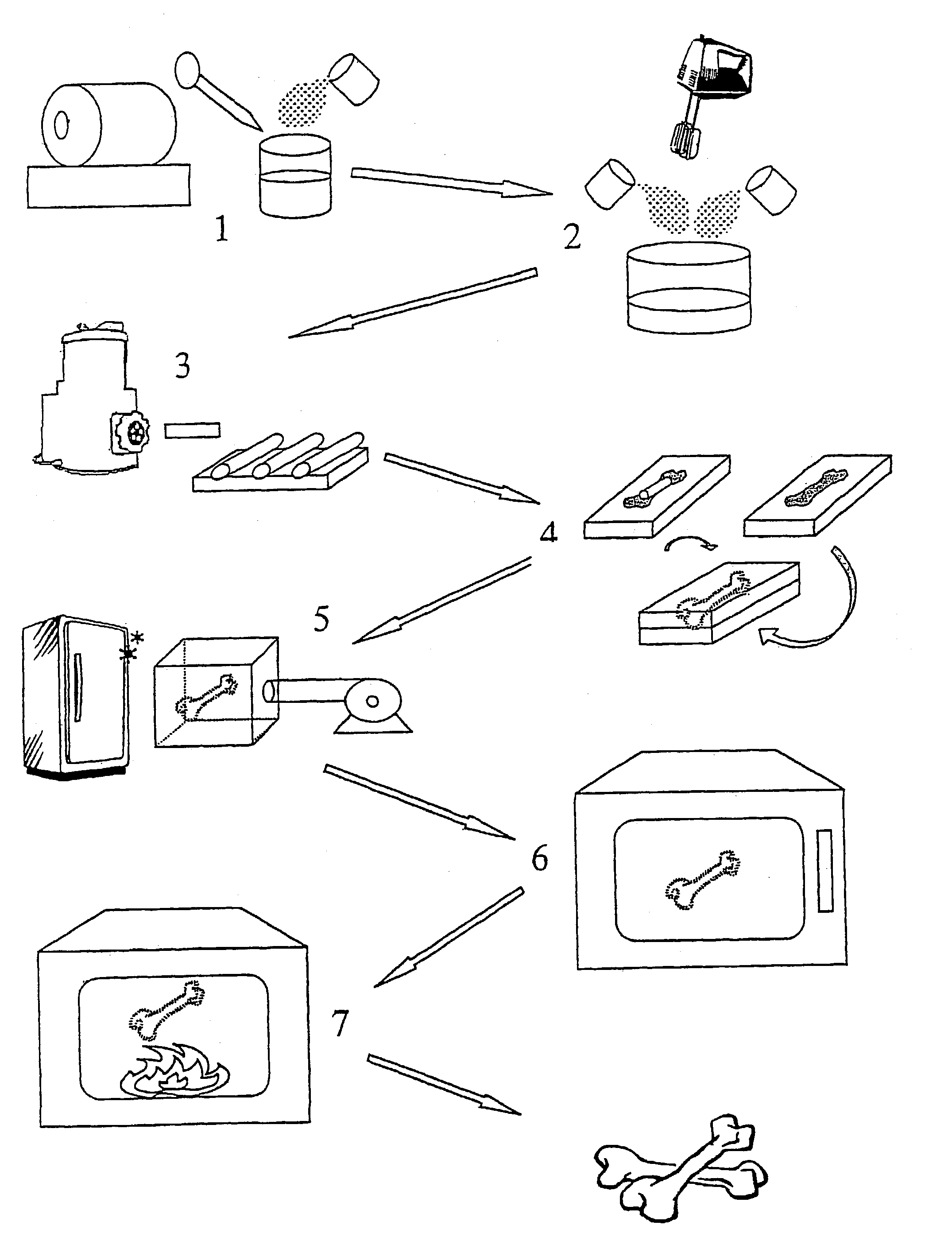
[0055]Commercial medical grade hydroxy apatite Ca10(PO4)6(OH)2 powder(ASTM F118588), particle size from 0.6 μm to 1 μm, was used to produce the synthetic porous bone graft. The first step is to make a slurry where the ingredients are:[0056]160 grams of hydroxy apatite powder[0057]70 millilitres of de-ionised water[0058]2 grams of ammonium polyacrylate.

These ingredients were initially homogeneously mixed in a plastic container with a spatula. When a uniform solution had been formed, mechanical agitation was applied with a double-bladed stirrer at approximately 1200 rpm for 5 minutes. This made approximately 115 ml of slurry. The slurry was then poured into a cylinder miller for further dispersion of the agglomerates; this was a polyethylene flask, 10 cm long and 6 cm diameter, containing 100 cm3 of high-density small Al2O3 cylinders. The cylinder miller was sealed and rotated at 120 rpm for 30 minutes to form a uniform slurry.

[0059]70 grams of fine, sieved wheat flour and 7 grams of ...

example 2

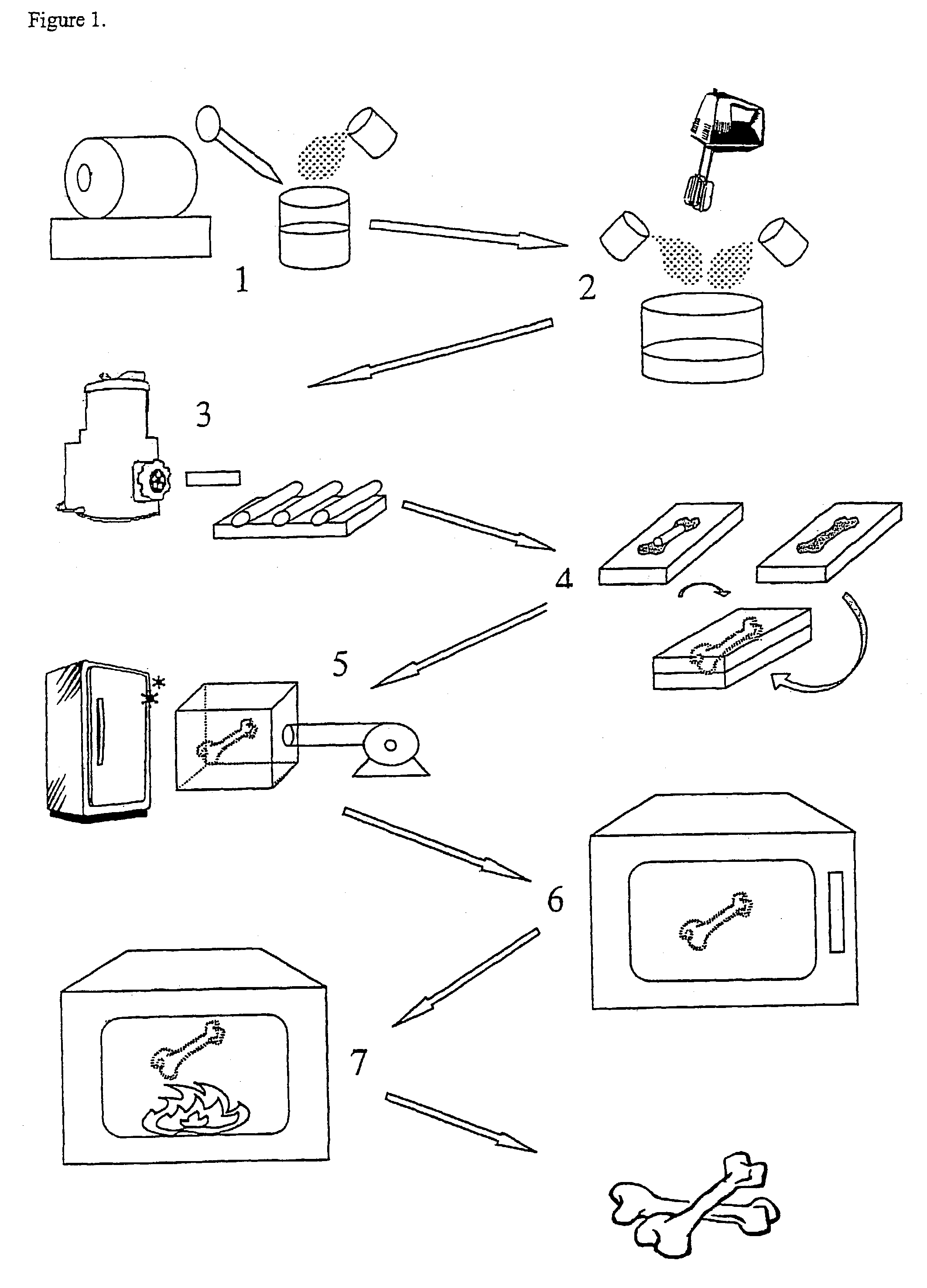
[0066]Sample of the porous HA product obtained in Example 1B were immersed in boiling HA slurry with an average particle size of 0.2 μm. The immersion times were from 30 minutes to 90 minutes with a 30 minutes interval and the slurry was stirred constantly. Afterwards the excess slurry was removed by a centrifuge process (from 2500 to 15000 rpm). The samples were subjected to the annealing process at 1280° C. for 5 hours.

[0067]A mechanical test of the samples was carried out using a Lloyd bench-top test machine fitted with a 2.5 kN load cell and a remote computer controlled unit. The load was applied to the specimens (average sample contact area is 0.8 cm2) with a crosshead speed of 0.1 mm per minute until brittle failure occurred. The results obtained are shown in FIG. 2. It can be seen that the compressive strength of the porous HA samples is increased as the immersion time increases.

example 3

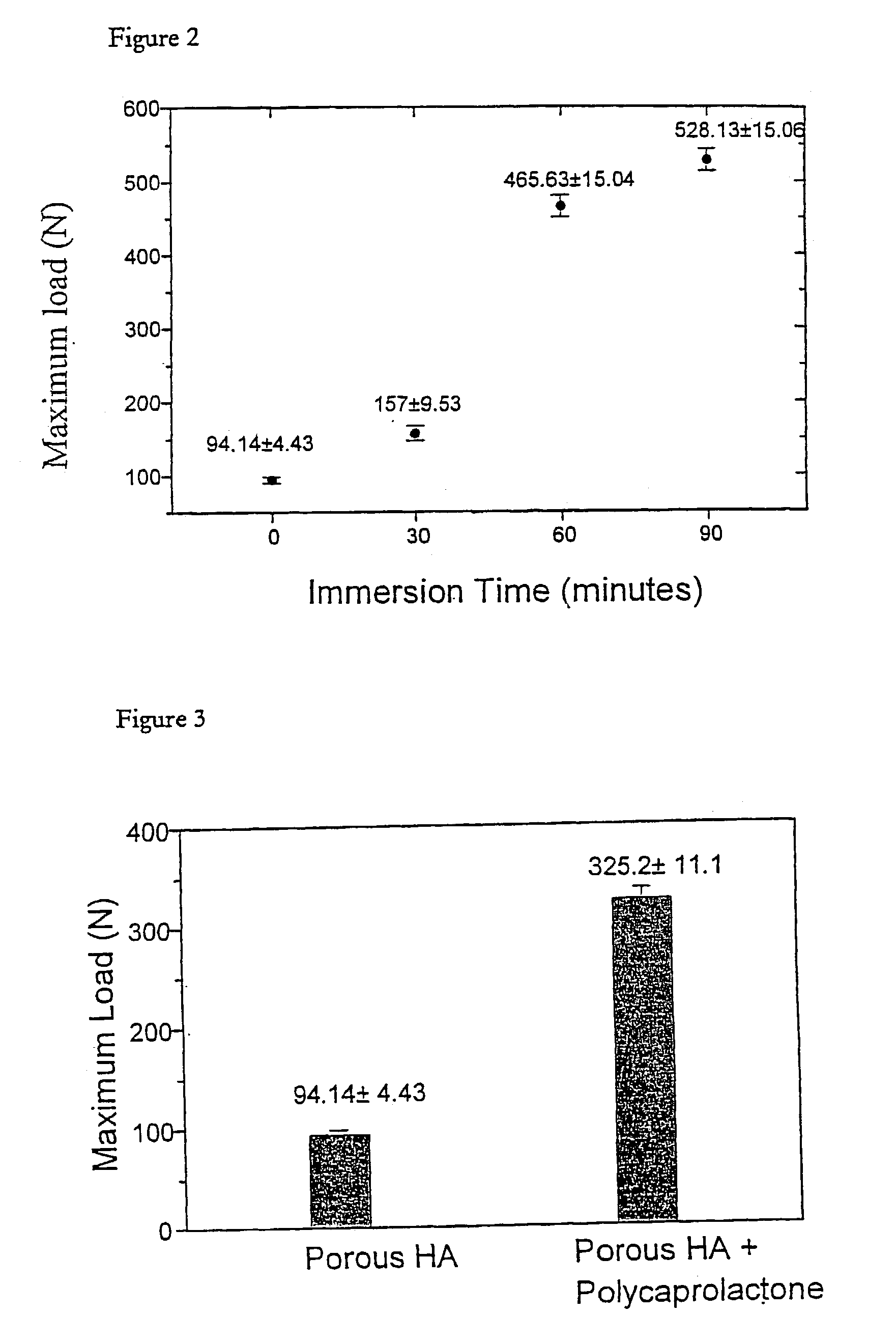
[0068]6 grams of PCL was melted in a 150 cc glass beaker by placing it in a 60° C. oven. After the solid PCL had melted to a clear sticky fluid, 20 ml acetone was added to dissolve the PCl and form a fluent solution. The viscosity of the solution was 0.8835±0.025 pas. Porous samples of Example 1B were then immersed in the solution and kept at boiling by placing it on a hot plate at constant temperature of 57° C.

[0069]After 20 minutes, the samples were removed and subjected to a centrifuge process (from 2500 to 15000 rpm) to remove any excess solution from the interconnected macroporous structure. The samples were then placed in a 60° C. oven to melt any blocking PCL in the macroporous structure and the centrifuge process was repeated.

[0070]The mechanical test of Example 2 was carried out. The results obtained as shown in FIG. 3. It can be seen that the PCL reinforced porous HA samples had a significantly increased compressive strength.

[0071]The porous properties of the tested sample...


PUM

PropertyMeasurementUnit
particle sizeaaaaaaaaaa
temperatureaaaaaaaaaa

Abstract

A process for preparing artificial bone is described which comprises: (i) preparing a mixture of a finely divided bio-compatible ceramic powder, an organic binder and a pore-forming agent in an inert liquid to form a body and causing at least some of the pore-forming agent to align along a common axis; (ii) optionally shaping the resulting body; (iii) allowing the pore-forming agent to form a porous structure in the body; (iv) heating the shaped body to a temperature sufficient to fix the porous structure and; (v) further heating the body to eliminate residues of organic binder and pore-forming agent and to fuse it.

Description

[0001]This application claims priority on GB0019003.3 filed on Aug. 4, 2000, GB0030295.0 filed on Dec. 12, 2000, as well as PCT / GB01 / 03397 filed on Jul. 27, 2001.[0002]This invention relates to the fabrication of synthetic bone in the form of a porous block from calcium phosphate or other ceramic powder. More particularly, this invention relates to a new manufacturing process to create a good synthetic bone graft with a controllable porous structure. It can be used to replace the autograft and allograft for orthopaedic surgeries including vertebrae repair, musculoskeletal reconstruction, fracture repair, hip and knee reconstruction, osseous augmentation procedures and oral / maxileofacial surgery.[0003]Currently the European bone graft market is dominated by autograft (bone taken from one part of the body and transferred to another part of the same individual) and allograft (bone taken from one individual and transferred to a different individual). In an autograft procedure, the bone ...

Claims


Application Information

Patent Timeline
Patent Type & Authority Patents(United States)
IPC IPC(8): B29C44/02A61L27/00A61F2/00A61F2/02A61F2/28A61F2/30A61F2/46A61L27/12C04B38/02C04B38/06
CPCA61F2/28A61F2/4644C04B38/062C04B38/02C04B35/636C04B35/63424C04B35/6261C04B35/447A61L27/12C04B41/0072C04B41/45C04B41/5025C04B22/106C04B40/0683C04B22/16C04B2235/96C04B2235/6565C04B2235/6562C04B2235/606C04B2235/6021C04B2235/5445C04B2235/3212C04B2111/00836A61L2430/02A61F2002/2817A61F2002/2835A61F2002/30062A61F2002/30957A61F2210/0004A61F2310/00293C04B2103/0001
Inventor LO, WEI JEN
Owner ORTHOGEM LTD
Why Eureka
Try Eureka