Motor and disk drive apparatus

a technology of motor and disk drive, which is applied in the direction of motor/generator/converter stopper, dynamo-electric converter control, instruments, etc., can solve the problems of conventional motor starting failure, difficult to carry out position detection operation, and described configuration of the above-mentioned conventional motor, etc., to achieve stable pwm sensorless driving

Inactive Publication Date: 2006-08-22
PANASONIC CORP
View PDF6 Cites 16 Cited by
  • Summary
  • Abstract
  • Description
  • Claims
  • Application Information

AI Technical Summary

Benefits of technology

[0007]In order to solve the problems in the above-mentioned conventional motors, the present invention is intended to provide a motor configured considering the influence of an induced voltage owing to the change in current due to PWM operation in PWM sensorless driving and being capable of carrying out stable PWM sensorless driving, and to provide a disk drive apparatus using this motor.

Problems solved by technology

In the conventional motor configured as described above, when high-frequency switching operation is OFF, the neutral point of the windings is pulled to the power supply voltage or the ground voltage, whereby it is difficult to carry out position detection operation.
However, the configuration of the above-mentioned conventional motor has problems described below.
Therefore, when the position detecting part 1030 erroneously detects the position of the rotor at the beginning of starting, sensorless driving is carried out while activation control is done according to the information detected erroneously; hence, there was a problem of having a high possibility of causing a starting failure in the conventional motor.
Since the position of the rotor is indefinite and the rotation speed thereof is low at the beginning of starting, the counter electromotive voltages induced in the windings 1011, 1012 and 1013 are small, and it is difficult to accurately detect the position of the rotor.
Hence, in the sensorless driving of the conventional motor, a starting failure may occur, resulting in a serious problem.
In particular, in the case when the motor is started by PWM sensorless operation, since an induced voltage owing to the change in current due to PWM operation is superimposed on the terminal voltage of a detection phase, the position of the rotor is erroneously detected under the influence of the induced voltage generated at the time of PWM sensorless starting, whereby a starting failure may occur.
In the motor having this kind of configuration, rotor movement time for initial position fixing is required; this causes a problem of extending starting time.

Method used


Image

  • Motor and disk drive apparatus
  • Motor and disk drive apparatus
  • Motor and disk drive apparatus

Examples


embodiment 1

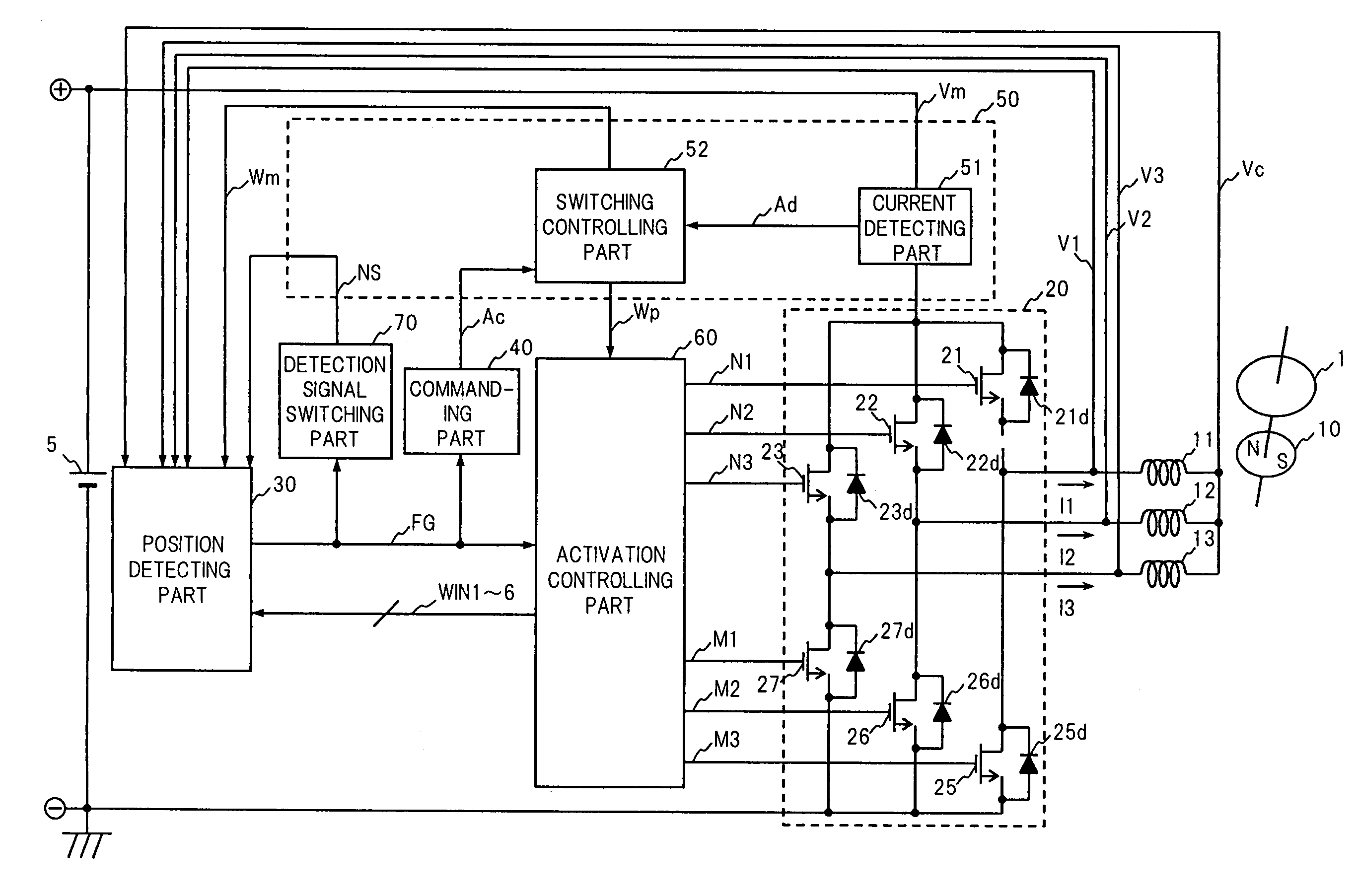
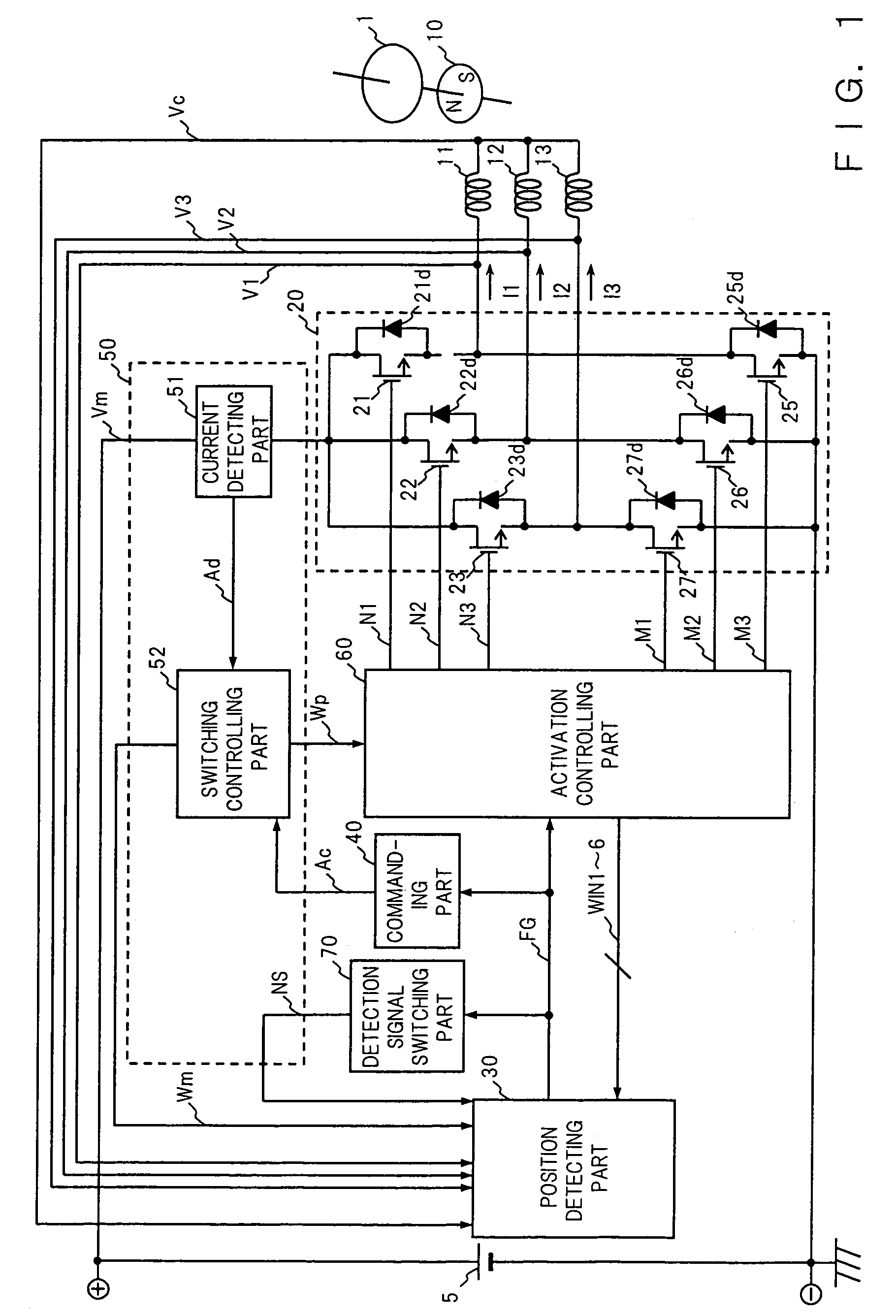
[0067]FIG. 1 to FIG. 4 show a motor in accordance with Embodiment 1 of the present invention. FIG. 1 is a block diagram showing the configuration of the motor in accordance with Embodiment 1.

[0068]In FIG. 1, a rotor 10 is provided with a field part generating field fluxes of a plurality of poles by using magnetic fluxes generated from a permanent magnet. Three-phase windings 11, 12 and 13 are provided on a stator serving as a stationary member, and the windings 11, 12 and 13 of the respective phases are disposed so as to be displaced from each other by an electrical angle of about 120 degrees with respect to the rotor 10. One terminal of each of the windings 11, 12 and 13 is connected to a power supplying part 20, and the other terminals are connected commonly. The three-phase windings 11, 12 and 13 generate three-phase magnetic fluxes by using three-phase drive currents I1, I2 and I3, and generates a drive force by virtue of the interaction with the rotor 10, thereby rotating the r...

embodiment 2

[0096]A motor in accordance with Embodiment 2 of the present invention will be described below. The motor in accordance with Embodiment 2 has substantially the same configuration as that of the above-mentioned Embodiment 1, and Embodiment 2 discloses a specific configuration of the detection signal switching part serving as state judging means in the motor. FIG. 7 is a block diagram showing the configuration of the detection signal switching part in the motor in accordance with Embodiment 2. In the explanations of Embodiment 2, the components having the same functions and configurations as those of Embodiment 1 are designated by the same numerals, and their explanations are omitted.

[0097]A detection signal switching part 170 serving as state judging means in the motor in accordance with Embodiment 2 will be described referring to FIG. 7. The detection signal switching part 170 comprises a counter circuit 171 and a latch circuit 172. The position detection pulse signal FG is input to...

embodiment 3

[0101]A motor in accordance with Embodiment 3 of the present invention will be described below. FIG. 8 is a block diagram showing the configuration of a detection signal switching part serving as state judging means in the motor in accordance with Embodiment 3. The configuration of the motor in accordance with Embodiment 3 is substantially the same as that of the motor in accordance with the above-mentioned Embodiment 1, except for the detection signal switching part 70, and a detection signal switching part 270, shown in FIG. 8, is provided instead of the detection signal switching part 70. Hence, in the explanations of Embodiment 3, the components having the same functions and configurations as those of Embodiment 1 are designated by the same numerals, and their explanations are omitted.

[0102]The detection signal switching part 270 serving as state judging means in the motor in accordance with Embodiment 3 will be described by using FIG. 8.

[0103]As shown in FIG. 8, the detection s...


PUM

PropertyMeasurementUnit
electrical angleaaaaaaaaaa
frequencyaaaaaaaaaa

Abstract

In a motor and a disk drive apparatus in accordance with the present invention, a position detecting part 30 comprises a detection signal switching circuit 39A, a noise elimination circuit 38 and a detection circuit 39B, and the detection signal switching circuit 39A is configured to output an inverted detection signal obtained by logically inverting a detection signal until the rotation speed reaches a predetermined rotation speed after the beginning of starting or until a position detection pulse signal FG is detected a predetermined number of times; position detection operation is carried out only during the ON operation of PWM, whereby PWM sensorless starting is carried out.

Description

BACKGROUND OF THE INVENTION[0001]The present invention relates to a motor for carrying out PWM sensorless driving and to a disk drive apparatus using the motor.[0002]FIG. 21 is a block diagram showing the configuration of a conventional motor. The operation of the conventional motor will be described briefly by using this FIG. 21. A rotor 1010 has a field part formed of a permanent magnet and generates a rotation force by virtue of interaction with three-phase windings 1011, 1012 and 1013. A power supplying part 1020 comprises three high-side power transistors and three low-side power transistors. The respective high-side and low-side power transistors are connected in series, and one terminal of each winding of a phase is connected to the connection point. The power supplying part 1020 comprising the high-side power transistors and the low-side power transistors supplies electric power to the windings 1011, 1012 and 1013. A position detecting part 1030 compares the terminal voltage...

Claims


Application Information

Patent Timeline
Patent Type & Authority Patents(United States)
IPC IPC(8): H02P7/00G11B19/28G11B19/20H02P6/06H02P6/08H02P6/16H02P6/182H02P6/21H02P6/28
CPCG11B19/2054G11B19/20
Inventor TAGOME, MASAKIMORI, HIDEAKINAGASE, HISANORIGOTOU, MAKOTO
Owner PANASONIC CORP
Why Eureka
Try Eureka