
Speed sensor for a power sensor module

a technology of speed sensor and power sensor, which is applied in the direction of force/torque/work measurement apparatus, instruments, manufacturing tools, etc., can solve the problems of power transfer or loss at the interface, many applications, such as automotive, rarely have power measurements available, etc., to achieve the effect of reducing assembly and packaging costs and reducing costs

Active Publication Date: 2006-08-22
HONEYWELL INT INC
View PDF25 Cites 58 Cited by
  • Summary
  • Abstract
  • Description
  • Claims
  • Application Information

AI Technical Summary

Benefits of technology

[0027]The magnetic target can be a multipole magnet, such as a north-south polarized ring magnet. By utilizing a multipole magnet target located on the rotating element, the weight, complexity and cost of targets necessary in conventional shaft speed sensors is eliminated.
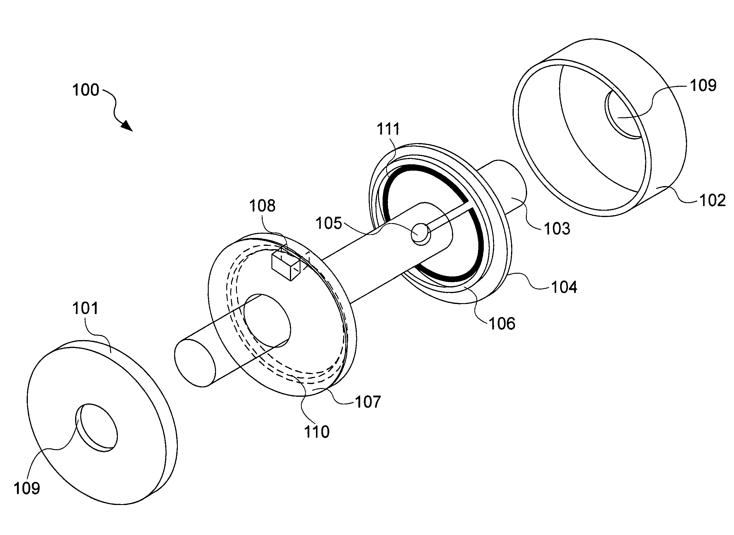
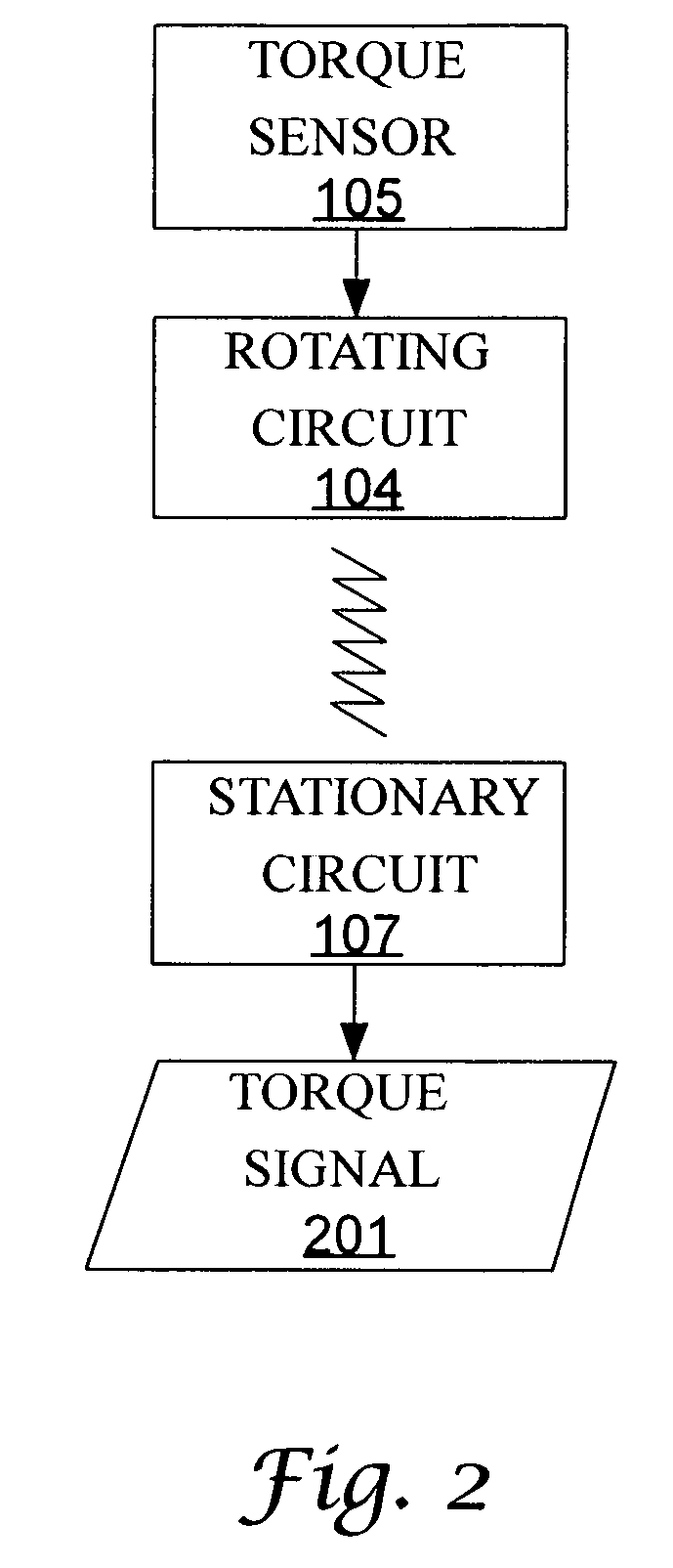
[0029]Torque measurement is accomplished by use of a torque sensor mounted on a rotating element, rotating circuitry fixed to the rotating element, a stationary circuit, and at least one processor. The torque sensor itself can be any of the current solutions that are well known to those skilled in any of the arts of engines, motors, or mechanical power. Additionally, a sensor based on one or more SAWs can be used for torque sensing. SAWs are relative newcomers to the area of torque sensing but they exhibit excellent sensitivity and are inexpensive. Additionally, SAWs typically require so little power that they can be powered, controlled, and read wirelessly.
[0031]The magnetic target can be mounted on the rotating circuitry. By mounting the magnetic target on the rotating circuit, assembly and packaging costs can be reduced. Furthermore, the magnetic speed sensor can be mounted on the stationary circuit further reducing costs. The rotating and stationary circuits can be formed as printed circuit boards (PCBs).

Problems solved by technology

Forcing a spinning plate's face against another plate's face causes power transfer or loss at the interface.
Any machine that similarly transfers mechanical power to a purpose has similar losses.
Many applications, such as automotive, rarely have power measurements available because they are extremely price sensitive.
The current solutions for power measurements are not appropriate for automotive engine, transmission, and drive train applications.

Method used


Image

  • Speed sensor for a power sensor module
  • Speed sensor for a power sensor module
  • Speed sensor for a power sensor module

Examples


Embodiment Construction

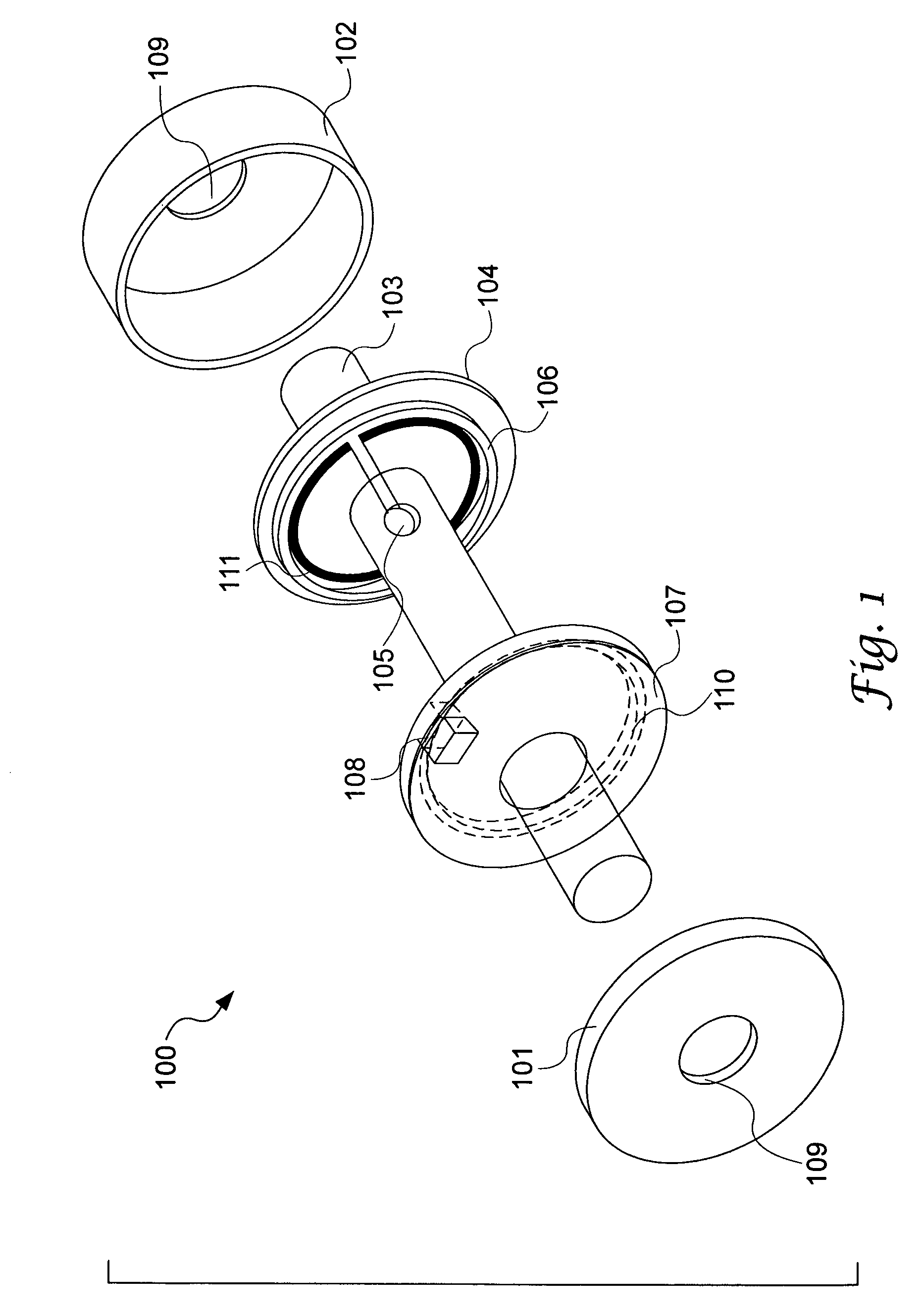
[0045]FIG. 1 of the accompanying drawings illustrates an exploded view of an aspect of the power sensor module 100. A stationary housing, comprising a left side housing 101 and a right side housing 102 encloses the other parts of the power sensor module. The each side housing has an aperture 109 through which a rotating shaft 103 passes. There are numerous equivalent ways to construct a housing. Inside the housing, the rotating shaft 103 passes through a stationary circuit 107 and a rotating circuit 104. The stationary and rotating circuits can be formed as PCBs. The rotating circuit 104 is fixed to the rotating shaft 103 such that it rotates also. A torque sensor 105 is also fixed to the rotating shaft 103. The torque sensor 105 is electrically connected to the rotating circuit 104. A magnetic speed sensor 108 is fixed to the stationary circuit and a target 106 is fixed to the rotating circuit.

[0046]In this particular embodiment, the target 106 consists of a multipole north-south p...


PUM

PropertyMeasurementUnit
torqueaaaaaaaaaa
magnetic fluxaaaaaaaaaa
magneticaaaaaaaaaa

Abstract

A power sensor module suitable for automotive and other high volume applications combines speed sensing and torque sensing operations into a single unit. A magnetic speed sensor is utilized for speed sensing. A power measurement can be derived from torque and speed. Combining torque sensing and speed sensing within a single module instead of using separate modules for each allows for reducing redundancies and lowering cost.

Description

TECHNICAL FIELD[0001]Embodiments relate to mechanical power sensing and mechanical power measurement. Embodiments also relate to constructing a power sensor module by packaging a torque sensor, a speed sensor, and related components within a single housing such that redundancies are exploited and costs reduced. Additionally, embodiments are related to a power sensor module having a wireless torque sensor and magnetic speed sensor.BACKGROUND OF THE INVENTION[0002]Machinery must often apply power generated by an engine or motor to a purpose such as drilling a hole or turning a wheel. As such, the machinery must transfer mechanical power. Mechanical power is transferred by rotating elements such as shafts, plates, and gears. For example, in a car the power generated by the engine must be transferred to the wheels. Most car engines generate power that is available on a rotating shaft called the crankshaft. The crankshaft is connected to a transmission via a clutch. A clutch effects rota...

Claims


Application Information

Patent Timeline
Patent Type & Authority Patents(United States)
IPC IPC(8): G01L3/02B25B23/14G01L3/10
CPCG01L3/242
Inventor O'BRIEN, GARY
Owner HONEYWELL INT INC
Learn More