
Logic system with adaptive supply voltage control

a logic system and supply voltage technology, applied in logic circuits, oscillator generators, pulse techniques, etc., can solve the problems of unsatisfactory increase of logic circuit delay, excessive power consumption, and little power available for logic circuits, and achieve the effect of reducing power consumption

Active Publication Date: 2006-08-22
XUESHAN TECH INC
View PDF2 Cites 16 Cited by
  • Summary
  • Abstract
  • Description
  • Claims
  • Application Information

AI Technical Summary

Benefits of technology

[0008]Therefore, an objective of the present invention is to provide a logic system with adaptive supply voltage control and an adaptive supply voltage control method for logic system, in which the supply voltage of the logic circuit is effectively controlled to minimize the power consumption.

Problems solved by technology

Unfortunately, reducing the power supply voltage results in an undesired increase of the logic circuit delay.
As such, this constant voltage setting results in excessive power consumption in most conditions.
In some specific applications, there is very little power available for the logic circuits.

Method used


Image

  • Logic system with adaptive supply voltage control
  • Logic system with adaptive supply voltage control
  • Logic system with adaptive supply voltage control

Examples


Embodiment Construction

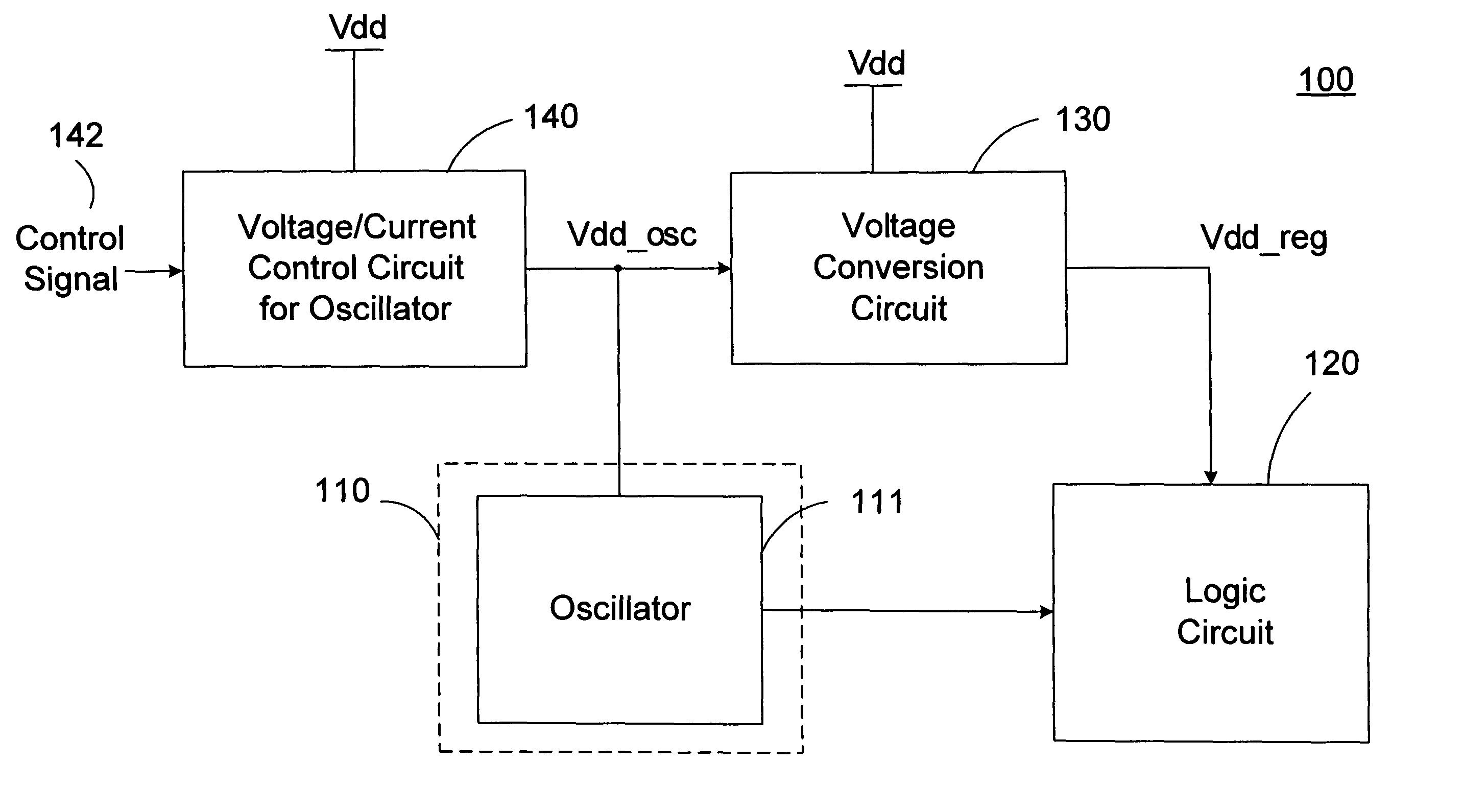
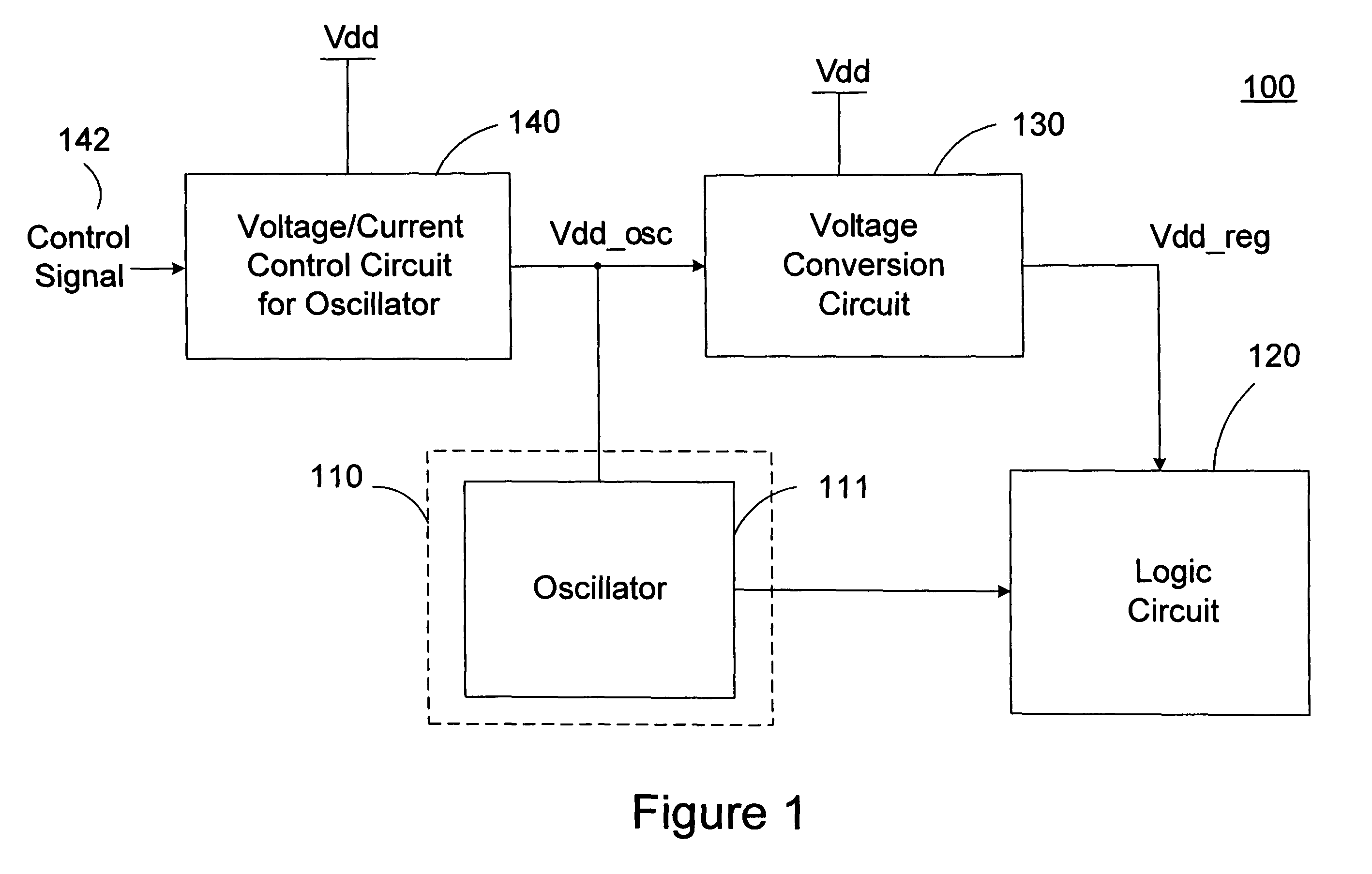
[0026]Please refer to FIG. 1, which shows the schematic circuit diagram of a preferred embodiment of the logic system with adaptive supply voltage control according to the present invention. As shown, the logic system 100 mainly comprises a logic circuit 120 clocked by a clock signal from a clock generating circuit 110 and a voltage conversion circuit 130 for regulating the supply voltage of the logic circuit 120.

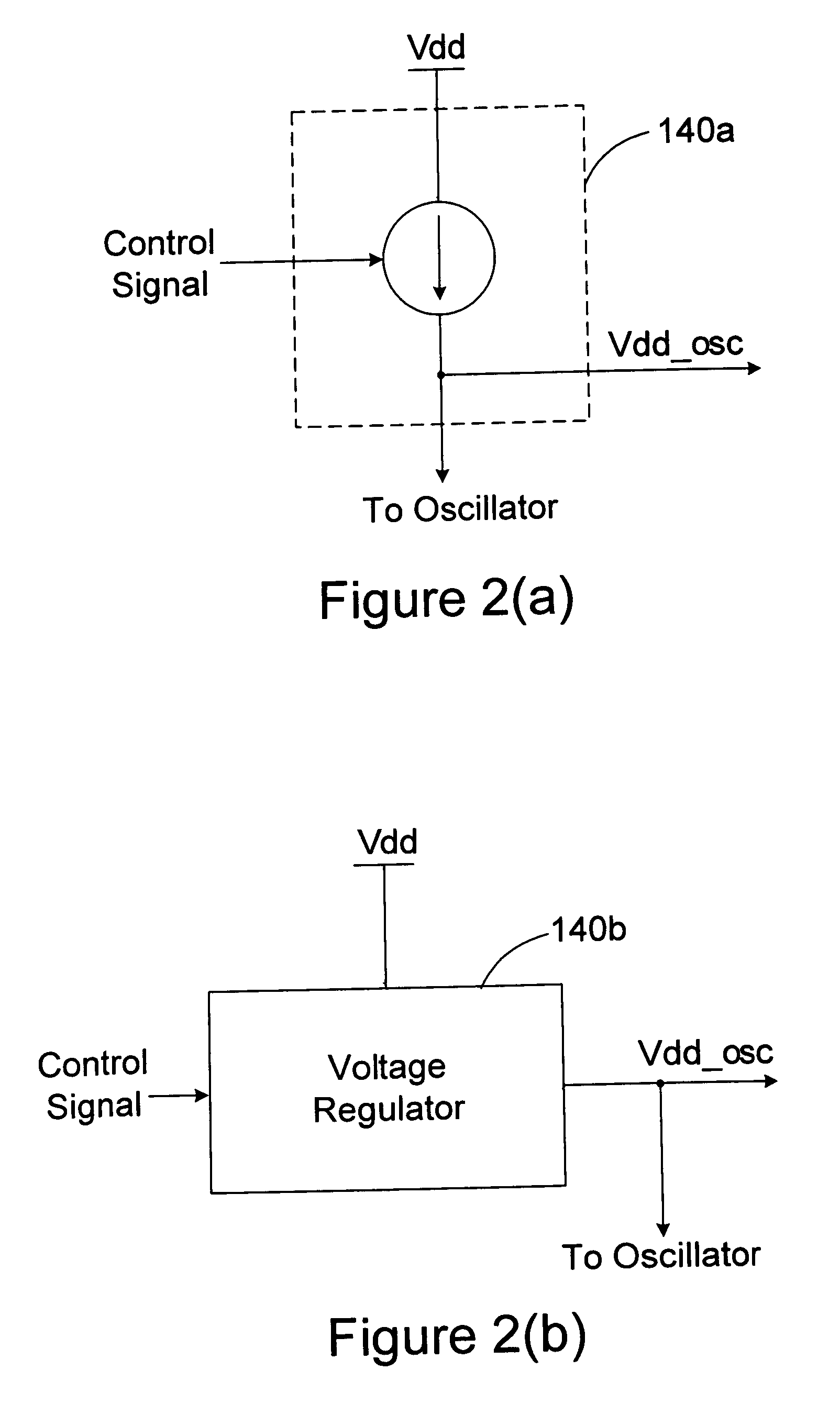
[0027]As shown in FIG. 1, the clock generating circuit 110 consists of a voltage-controlled or current-controlled oscillator 111, which is driven by a voltage / current control circuit 140. A control signal 142 controls the voltage / current control circuit 140 to produce a driving voltage / current to the oscillator 111 for generating a clock signal of a predetermined operating frequency. This can be achieved by various conventional techniques, such as a PLL (phase-locked loop) circuit. FIGS. 2(a) and 2(b) illustrate examples of the voltage / current control circuit for oscillator...


PUM


Abstract

A logic system with adaptive supply voltage control comprising a logic circuit clocked by a clock signal from a clock generating circuit and a voltage conversion circuit for generating a dynamically regulated supply voltage for powering the logic circuit. A critical path delay of the logic circuit is designed to be equal to or shorter than a period of the clock signal. The voltage conversion circuit dynamically regulates the supply voltage of the logic circuit based on a bias voltage of the clock generating circuit. According to the invention, the power consumption is effectively minimized while ensuring the logic circuit to function correctly throughout all conditions.

Description

CROSS-REFERENCE TO RELATED APPLICATIONS[0001]This application is based upon and claims the benefit of U.S. provisional application No. 60 / 398,613 filed Jul. 26, 2002, the contents of which are incorporated herein by reference.BACKGROUND OF THE INVENTION[0002]1. Field of the Invention[0003]This invention relates to an adaptive supply voltage control technology for minimizing power consumption, particularly to a low power logic circuit with adaptive supply voltage control and an adaptive supply voltage control method for low power logic circuit.[0004]2. Description of the Related Art[0005]In conventional low power logic circuit design, lowering the power supply voltage of a circuit is generally known as the most effective way to reduce power dissipation, as the power consumption is proportional to the square of the supply voltage. Unfortunately, reducing the power supply voltage results in an undesired increase of the logic circuit delay. Although high supply voltage is not necessary ...

Claims


Application Information

Patent Timeline
Patent Type & Authority Patents(United States)
IPC IPC(8): H03B5/04H03K19/00
CPCH03K19/0016H03L7/0816H03L7/0802
Inventor SMITH, STERLING
Owner XUESHAN TECH INC
Learn More