Satellite dish sighting apparatus and alignment system

Inactive Publication Date: 2006-08-22
PAQUETTE FRED
View PDF44 Cites 16 Cited by
  • Summary
  • Abstract
  • Description
  • Claims
  • Application Information

AI Technical Summary

Benefits of technology

[0020]An advantage of the present invention is that it permits dispensing with finding a level spot on which to place the dish or dish stand.
[0021]Another advantage of the present invention is that the dish can be adjusted and aimed completely independent of the mounting pole.
[0022]Yet another advantage of the present invention is that inaccurately stamped markings on the dish become completely irrelevant to the dish alignment.
[0023]Yet another advantage of the present invention is that problems associated with alignment of one axis causing misalignment of another axis are avoided as all axes are adjusted simultaneously.
[0024]Yet another advantage of the present invention is that the time to align a dish, and time to wait for the receiver to “catch up” with the signal and show up on the television, are elimina

Problems solved by technology

If the dish mounting pole is not perfectly level, not only are the molded or stamped alignment markings on the dish inaccurate, but as one axis of the dish alignment is adjusted, the alignment of the other axis, if it was previously set, becomes misaligned.
The conventional process for aligning a satellite dish can become an extremely aggravating process.
The current dual low noise block down converter satellite dishes which employ a single feed horn (LNB) to pick up waves from two satellites placed close to each other in space in geosynchronous orbit and newer modern multi-satellite dishes (which can pick up waves from three satellites) are even more difficult as they require an additional axis of the satellite dish (generally referred to as “skew”, “tilt” or “polarization”) to also be accurately aligned in order to receive signals from either two or three satellites at the same time.
Thus it is a time-consuming and difficult procedure to align a dish for optimal reception from a given satellite.
However, all devices and methods heretofore described have significant limitations.
For example, U.S. Pat. No. 4,495,706 discloses an alignment gage that determines azimuth and altitude, but does not provide for a third skew axis.
It also lacks a method or structure for determining obstruction

Method used


Image

  • Satellite dish sighting apparatus and alignment system
  • Satellite dish sighting apparatus and alignment system
  • Satellite dish sighting apparatus and alignment system

Examples


Embodiment Construction

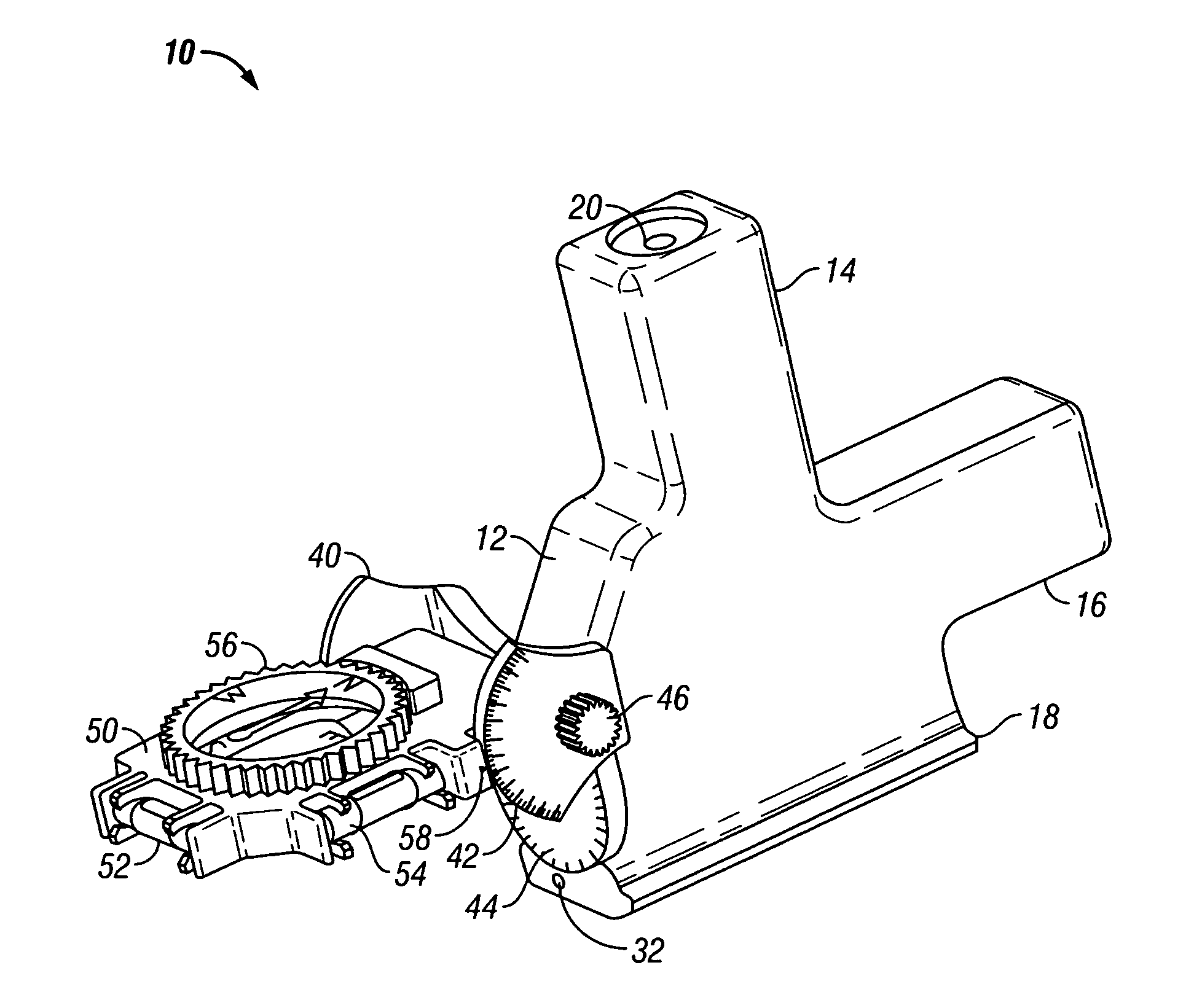
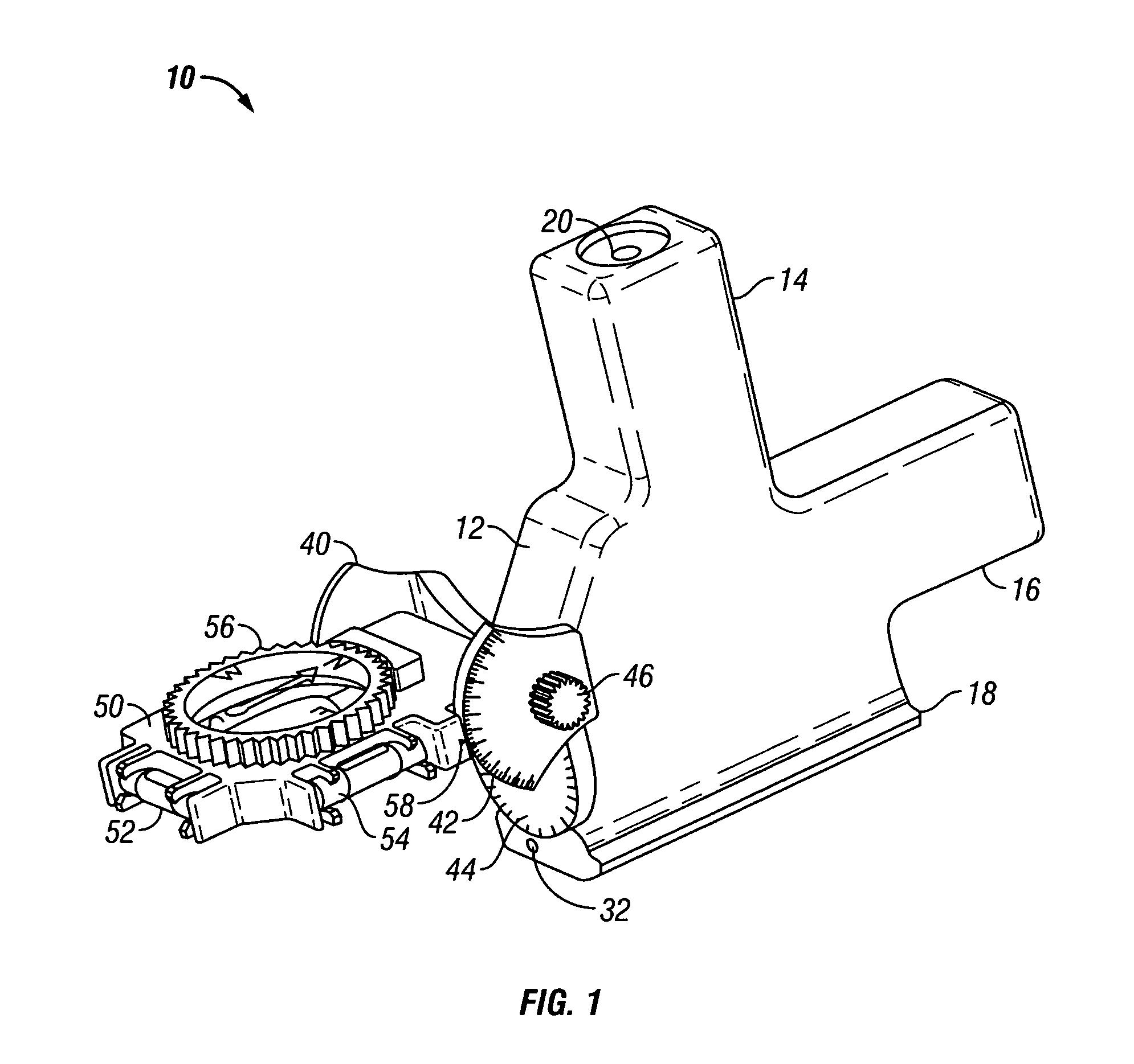
[0037]Reference is now made to the drawings which illustrate a preferred embodiment of the invention. As shown therein, FIG. 1 shows a side view of the preferred embodiment of the present invention. FIG. 1 shows the sighting portion with the compass portion attached to the back of the sighting portion.

[0038]The preferred embodiment of sighting device 10 is made from a hard plastic or other similar material, most preferably non-ferrous and of a material which does not interfere with a compass (i.e. made from materials that do not exhibit ferromagnetism). Thus PVC, ABS and similar plastics, made by machining, injection molding or similar means, may be employed in the invention.

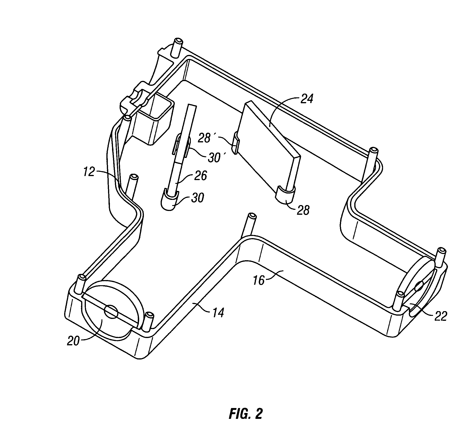
[0039]The sighting device 10 includes a body 12, preferably made by machining or injection molding of plastic materials, which includes a viewing tube made up of viewing arm 14 and line of sight arm 16. In a preferred embodiment, the two arms 14 and 16 are disposed at a ninety degree angle (90°) one to the other...


PUM


Abstract

An apparatus and method for setting up a satellite dish to receive satellite signals, including television satellite signals, with precise positioning and aiming of the satellite dish, including determination of a clear line of sight, azimuth orientation, elevation angle and skew or tilt angle. The apparatus includes a line of sight mechanism removably attachable to a satellite dish.

Description

CROSS-REFERENCE TO RELATED APPLICATION[0001]This application claims the benefit of the filing of U.S. Provisional Patent Application Ser. No. 60 / 539,839 entitled “Satellite Dish Sighting Apparatus And Dish Alignment System”, filed on Jan. 28, 2004, and the specification thereof is incorporated herein by reference.BACKGROUND OF THE INVENTION[0002]1. Field of the Invention (Technical Field)[0003]The present invention relates to an apparatus, system and method for sighting, setting up and aligning a satellite dish to receive satellite signals, including but not limited to television satellite signals.[0004]2. Description of Related Art[0005]Note that the following discussion refers to a number of publications by author(s) and year of publication, and that due to recent publication dates certain publications are not to be considered as prior art vis-a-vis the present invention. Discussion of such publications herein is given for more complete background and is not to be construed as an ...

Claims


Application Information

Patent Timeline
IPC IPC(8): H01Q3/00
CPCH01Q1/125
Inventor PAQUETTE, FRED
Owner PAQUETTE FRED
Why Eureka
Try Eureka