
Head gimbal assembly and method for manufacturing the same

a technology of head gimbal and assembly, which is applied in the direction of maintaining the head carrier alignment, recording information storage, instruments, etc., can solve the problems of insufficient measures to prevent electrostatic discharge, damage to discharge unfortunately damages the magnetic head element at a constant rate, so as to prevent the damage of electrostatic discharge, reduce the contact resistance, and reduce the contact resistance

Inactive Publication Date: 2006-08-22
TDK CORPARATION
View PDF9 Cites 12 Cited by
  • Summary
  • Abstract
  • Description
  • Claims
  • Application Information

AI Technical Summary

Benefits of technology

[0008]An object of the present invention, therefore, is to provide a head gimbal assembly and its manufacturing method for preventing damage from electrostatic discharge more efficiently.
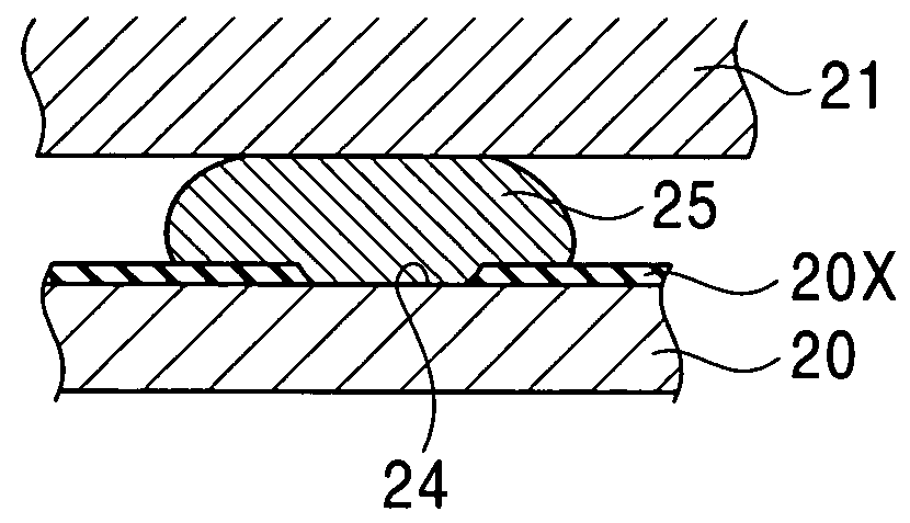
[0011]Thus, bonding the slider to the film-removed region of the slider-bonding surface of the flexure with the conductive adhesive resin allows a significant decrease in the contact resistance. This prevents the damage from the electrostatic discharge. Mechanical scratching is the easiest way to form the film-removed region. The slider, if mechanically scratched in the atmosphere, is preferably bonded to the flexure with the conductive adhesive resin immediately after the scratching (before formation of the oxide film). The mechanical scratching and the bonding are more preferably carried out in an inert atmosphere.
[0012]The film-removed region may be formed by laser irradiation or electrical discharge in an inert atmosphere. This prevents re-formation of the oxide film, which is more persistent, at a laser-irradiated or discharge-machined region. The flexure and the slider are most preferably bonded with the conductive adhesive resin in the same inert atmosphere immediately after the laser irradiation or the discharge. However, experimental results show that re-formation of the oxide film on the film-removed region takes several days or weeks. Therefore, a certain amount of decrease in the contact resistance is ensured by bonding the slider to the film-removed region in the atmosphere as soon as possible after the removal of the oxide film by the laser irradiation or the discharge.
[0013]Accordingly, the present invention provides a head gimbal assembly having a gimbal suspension that includes a metal flexure bonded to a slider having a magnetic head element. This head gimbal assembly prevents electrostatic discharge more efficiently, which damages the magnetic head element. The present invention further provides a method for manufacturing the head gimbal assembly.

Problems solved by technology

In this head gimbal assembly, a charged slider may cause electrostatic discharge (ESD), which damages the magnetic head element on the slider.
However, these conventional measures are insufficient to prevent the electrostatic discharge; in fact, the electrostatic discharge unfortunately damages the magnetic head element at a constant rate.

Method used


Image

  • Head gimbal assembly and method for manufacturing the same
  • Head gimbal assembly and method for manufacturing the same
  • Head gimbal assembly and method for manufacturing the same

Examples


Embodiment Construction

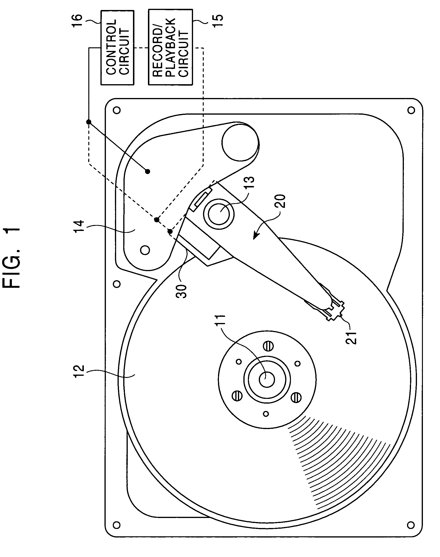
[0021]FIG. 1 shows the entire structure of a hard disc drive having a head gimbal assembly according to the present embodiment. A hard disc 12, which is a magnetic disc, rotates around a rotating shaft 11. Another rotating shaft 13, which is disposed adjacent to the hard disc 12, supports the base of a gimbal suspension 20. This gimbal suspension 20 is rotatable around the rotating shaft 13. A free end of the gimbal suspension 20 is bonded to a slider 21 having a thin film magnetic head element such as a magnetoresistive element or a giant magnetoresistive element. When an actuator 14 rotates the gimbal suspension 20 around the rotating shaft 13, the slider 21 reciprocates substantially in the radial direction of the hard disc 12.

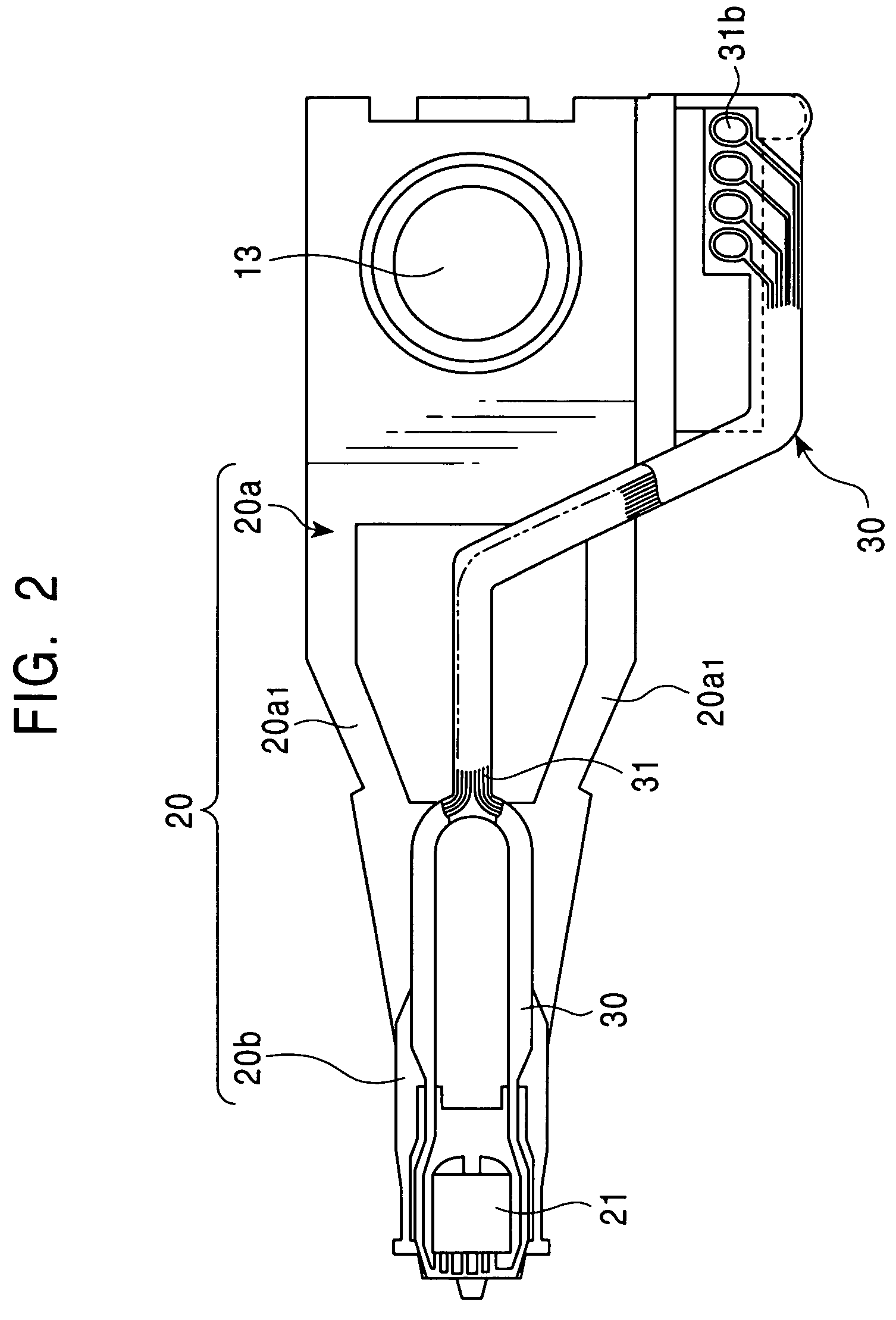
[0022]Referring to FIG. 2, the gimbal suspension 20 includes a load beam 20a, which is the base of the gimbal suspension 20 supported by the rotating shaft 13, and a stainless-steel flexure (flexure base) 20b, which is laser-welded to the leading end of the...


PUM

PropertyMeasurementUnit
thicknessaaaaaaaaaa
conductiveaaaaaaaaaa
breakdown voltageaaaaaaaaaa

Abstract

A head gimbal assembly has a gimbal suspension that includes a metal flexure bonded to a slider having a magnetic head element. This head gimbal assembly prevents damage from electrostatic discharge more efficiently. In the head gimbal assembly, a region of an oxide film on a slider-bonding surface of the flexure is completely or incompletely removed to form a film-removed region, and conductive adhesive resin is disposed between the film-removed region and the slider.

Description

[0001]This application claims the benefit of priority to Japanese Patent Application 2002-304632, filed on Oct. 18, 2002.BACKGROUND OF THE INVENTION[0002]1. Field of the Invention[0003]The present invention relates to head gimbal assemblies (HGAs) and methods for manufacturing the head gimbal assemblies.[0004]2. Description of the Related Art[0005]Head gimbal assemblies are widely used for hard disc drives (HDDs). Such a head gimbal assembly includes a load beam, a metal flexure fixed on the leading end of the load beam, and a slider bonded on an end of the flexure. This slider has a thin film magnetic head element such as a magnetoresistive element (MR element) or a giant magnetoresistive element (GMR element). In this head gimbal assembly, a charged slider may cause electrostatic discharge (ESD), which damages the magnetic head element on the slider. To solve this problem, conductive adhesive resin is conventionally disposed between the flexure and the slider to dissipate the char...

Claims


Application Information

Patent Timeline
Patent Type & Authority Patents(United States)
IPC IPC(8): G11B21/20G11B21/21G11B5/48H05K1/05H05K3/32
CPCG11B5/4826H05K3/321H05K1/053
Inventor MOTONISHI, MICHIHARUWATANABE, MITSURU
Owner TDK CORPARATION
Learn More