Digital precoding filter for a transmission filter

a transmission filter and digital precoding technology, applied in the field of digital precoding filters for transmission filters, can solve the problems of relatively high requirements made complex circuit design in terms of circuitry, etc., and achieve the effect of minimizing the crest factor of the signal output and low requirements placed on the circuitry of the line driver of the transmitter

Inactive Publication Date: 2006-08-22
LANTIQ BET GMBH & CO KG
View PDF9 Cites 1 Cited by
  • Summary
  • Abstract
  • Description
  • Claims
  • Application Information

AI Technical Summary

Benefits of technology

[0010]It is therefore the object of the present invention to create a digital preceding filter for a transmission filter for the purpose of minimizing the crest factor of the signal output by the transmission filters such that the requirements placed on the circuitry of the line driver of the transmitter are low.

Problems solved by technology

The line driver, which is used in the case of an SDL (symetrical [sic] digital subscriber line), for example, is of complex design in terms of circuitry, since because of the data transmission in upstream and downstream directions in the same frequency band is performed [sic] and there is a consequent need for echo compensation in the receiver.
The circuitry arrangement according to the prior art as it is illustrated in FIG. 2 therefore has the disadvantage that, owing to the high crest factor of the output signal output by the digital transmission filter, the requirements made on the circuitry of the line driver are likewise relatively high.

Method used


Image

  • Digital precoding filter for a transmission filter
  • Digital precoding filter for a transmission filter
  • Digital precoding filter for a transmission filter

Examples


Embodiment Construction

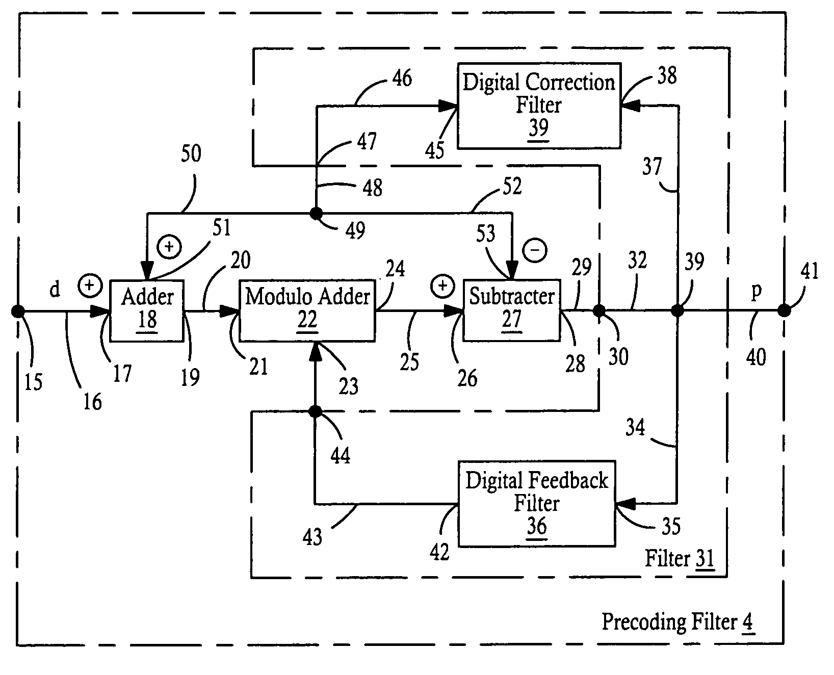
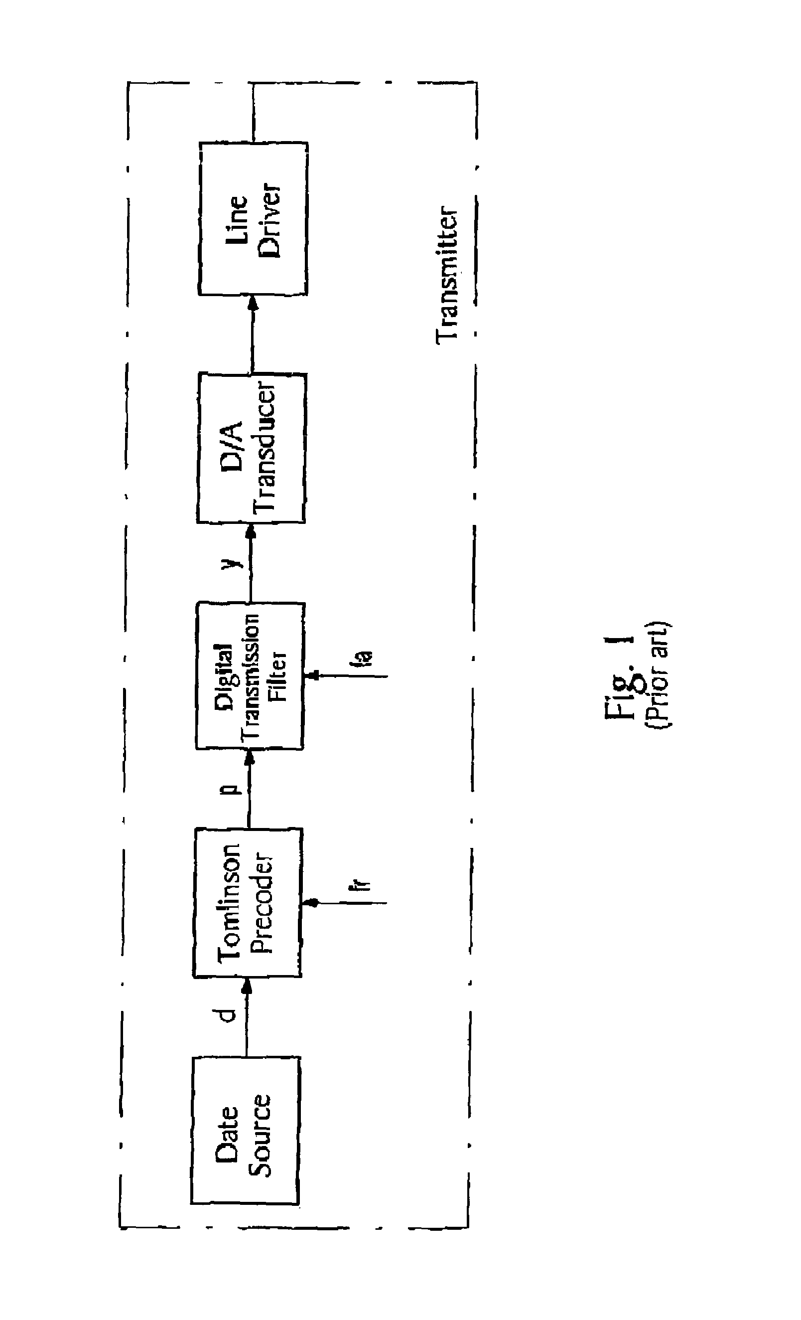
[0036]FIG. 4 shows a transmitter 1 with a data symbol source 2 which outputs source data symbols d with a symbol clock frequency fT via a signal line 3 to a digital precoding filter 4 according to the invention, which filters the received data symbols and outputs the filtered transmission data symbols p via a line 5 to a downstream transmission filter 6. The transmission filter 6 preferably includes a digital transmission filter 7 which is connected via a line 8 to a digital-to-analog converter 9, which converts the filtered data symbols into an analog signal. An analog smoothing filter 11 is connected downstream of the digital-to-analog converter 9 via a line 10. The analog smoothing filter 11 is connected on the output side via a line 12 to a line driver 13 whose output 14 forms the output of the transmitter 1 and is connected via a transmission line to a receiver (not illustrated).

[0037]The source data symbols d are output by the data symbol source 2 with the symbol clock frequen...


PUM


Abstract

Digital precoding filter for a transmission filter (6) for minimizing the chrest [sic] factor of the signal (y) output by the transmission filter (6), having a modulo adder (22) of the source data symbols which are received from a data symbol source (2) at a signal input (15) of the precoding filter (4), and added with fedback filtered transmission data symbols to transmission output data symbols (p) which are output to the downstream transmission filter (6) via a signal output (41) of the precoding filter (4); and a digital feedback filter (36) which filters the transmission output data symbols present at the signal output (41) and feeds them back to the modulo adder (22), and that [sic] a digital correction filter (39) is connected to the signal output (41), the filter coefficients of the digital correction filter (39) being set as a function of the normalized pulse response of the transmission filter (6) in the case of that sampling phase (τ) for which the output signal of the transmission filter (6) has a maximum value.

Description

TECHNICAL FIELD[0001]The invention relates to a digital precoding filter for a transmission filter for minimizing the crest factor of the signal output by the transmission filter.BACKGROUND ART[0002]FIG. 1 shows a transmitter according to the prior art. A data source generates source data symbols which is [sic] output by the data symbol source via a line to what is termed a Tomlinson precoding filter. The Tomlinson precoding filter is generally a non-recursive digital filter whose filter coefficient [sic] are set as a function of the properties of the data transmission line. The Tomlinson precoding filter receives the source data symbols d from the data source with a symbol clock frequency fT. The source data symbols d are generally multi-level symbols and have a number of levels N. The Tomlinson precoding filter processes the received source data symbols d with the symbol clock frequency fT and outputs output values p to a downstream digital transmission filter. As a result of the ...

Claims


Application Information

Patent Timeline
Patent Type & Authority Patents(United States)
IPC IPC(8): H04L25/49H04B15/00H04L25/03H04L25/497
CPCH04L25/03343H04L25/4975H04L25/497
Inventor SCHENK, HEINRICH
Owner LANTIQ BET GMBH & CO KG
Why Eureka
Try Eureka