
Test system, test method and test program for an integrated circuit by IDDQ testing

a technology of integrated circuit and test system, applied in the direction of testing circuits, semiconductor/solid-state device testing/measurement, testing/measurement of instruments, etc., can solve the problems of process deviating to some degree from the center condition, difficult to control the various process parameters, and large deviation of process conditions

Inactive Publication Date: 2006-08-22
KK TOSHIBA
View PDF18 Cites 30 Cited by
  • Summary
  • Abstract
  • Description
  • Claims
  • Application Information

AI Technical Summary

Problems solved by technology

Generally, in the mass production of integrated circuits however, process conditions often deviate from the targeted process center condition, and in particular, in fine processes of less than 0.25 μm, which are generally called deep sub-micron (DSM) processes, it becomes difficult to control the various process parameters and hence the deviation of process conditions tends to be great as the miniaturization advances.
Thus, even in a relatively well-controlled production factory, the process often deviates from the center condition to some degree.
Accordingly, many fault-free products are treated as faulty products, and integrated circuit manufacturers suffer a great loss.
However, on the contrary, if the range of judging fault-free products is widened in fear of such a loss, it follows that faulty products are misjudged to be fault-free products and are shipped erroneously, and this might result in the loss of customer trust.
Thus, in the test method of the quiescent supply current IDDQ disclosed in Japanese Patent Laid Open Publication No. 2001-91566, it has been difficult to make a high-reliability judgment on whether an integrated circuit is a fault-free (defect-free) or a faulty (defective) product, by appropriately adapting to dispersion in process conditions which are usually supposed in the fields of mass production.
Then, practical use of this test method in actual fields of mass production of integrated circuit has been difficult.

Method used


Image

  • Test system, test method and test program for an integrated circuit by IDDQ testing
  • Test system, test method and test program for an integrated circuit by IDDQ testing
  • Test system, test method and test program for an integrated circuit by IDDQ testing

Examples


first embodiment

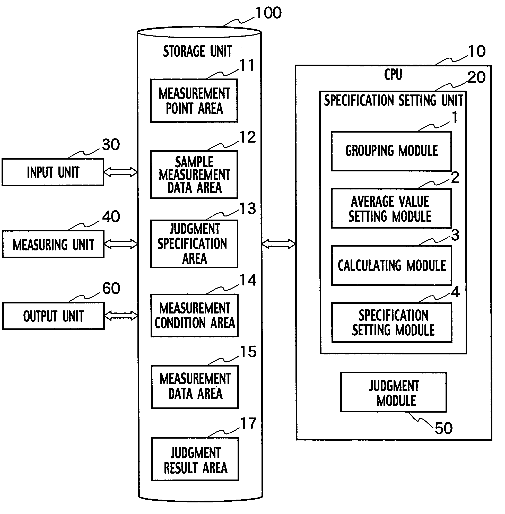
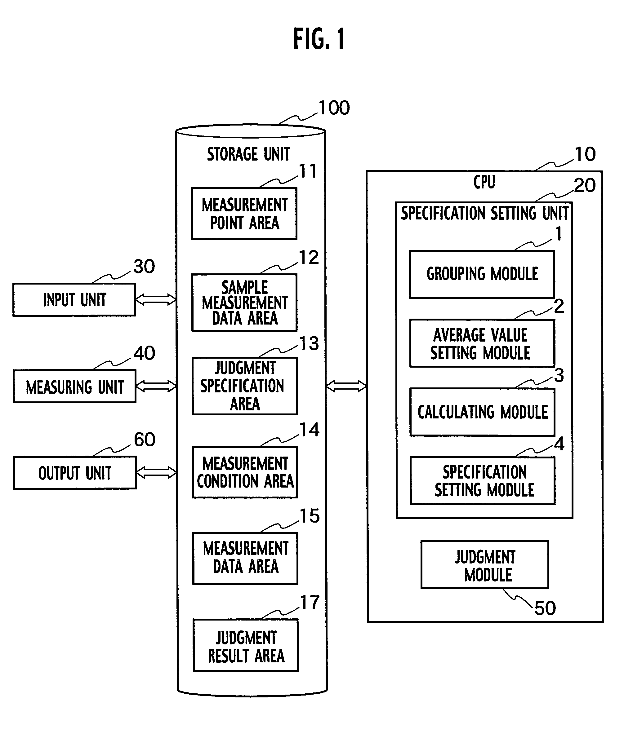
[0027]A test system related to the first embodiment of the present invention includes, as shown in FIG. 1, a CPU unit 10, an input unit 30, a storage unit 100, a measuring unit 40 and an output unit 60. The storage unit 100 also includes a measurement point area 11, a sample measurement data area 12, a judgment specification area 13, a measurement condition area 14, a measurement data area 15 and a judgment result area 17. Furthermore, the CPU 10 includes a specification setting unit 20 and a judgment module 50. The specification setting unit 20 includes a grouping module 1 which groups measurement points on the basis of values of quiescent supply current IDDQ of measurement points and sets measurement point groups, an average value setting module 2, which sets a weighted average value at which the sum of dispersion of quiescent supply current IDDQ due to differences in the process conditions of the measurement point groups becomes a minimum, a calculating module 3 which calculates ...

second embodiment

[0070]A test system related to the second embodiment of the present invention includes, as shown in FIG. 10, a CPU unit 10, an input unit 30, a storage unit 100, a measuring unit 40 and an output unit 60. The storage unit 100 also includes a measurement point area 11, a judgment specification area 13, a measurement condition area 14, a measurement data area 15, a simulation data area 16 and a judgment result area 17. Furthermore, the CPU 10 includes a specification setting unit 20 and a judgment module 50. The specification setting unit 20 includes a grouping module 1 which groups measurement points on the basis of values of the quiescent supply current IDDQ of measurement points and sets measurement point groups, a average value setting module 2 which sets a weighted average value at which the sum of dispersion of the quiescent supply current IDDQ due to difference in the process conditions of the measurement point groups becomes a minimum, a calculating module 3 which calculates a...


PUM


Abstract

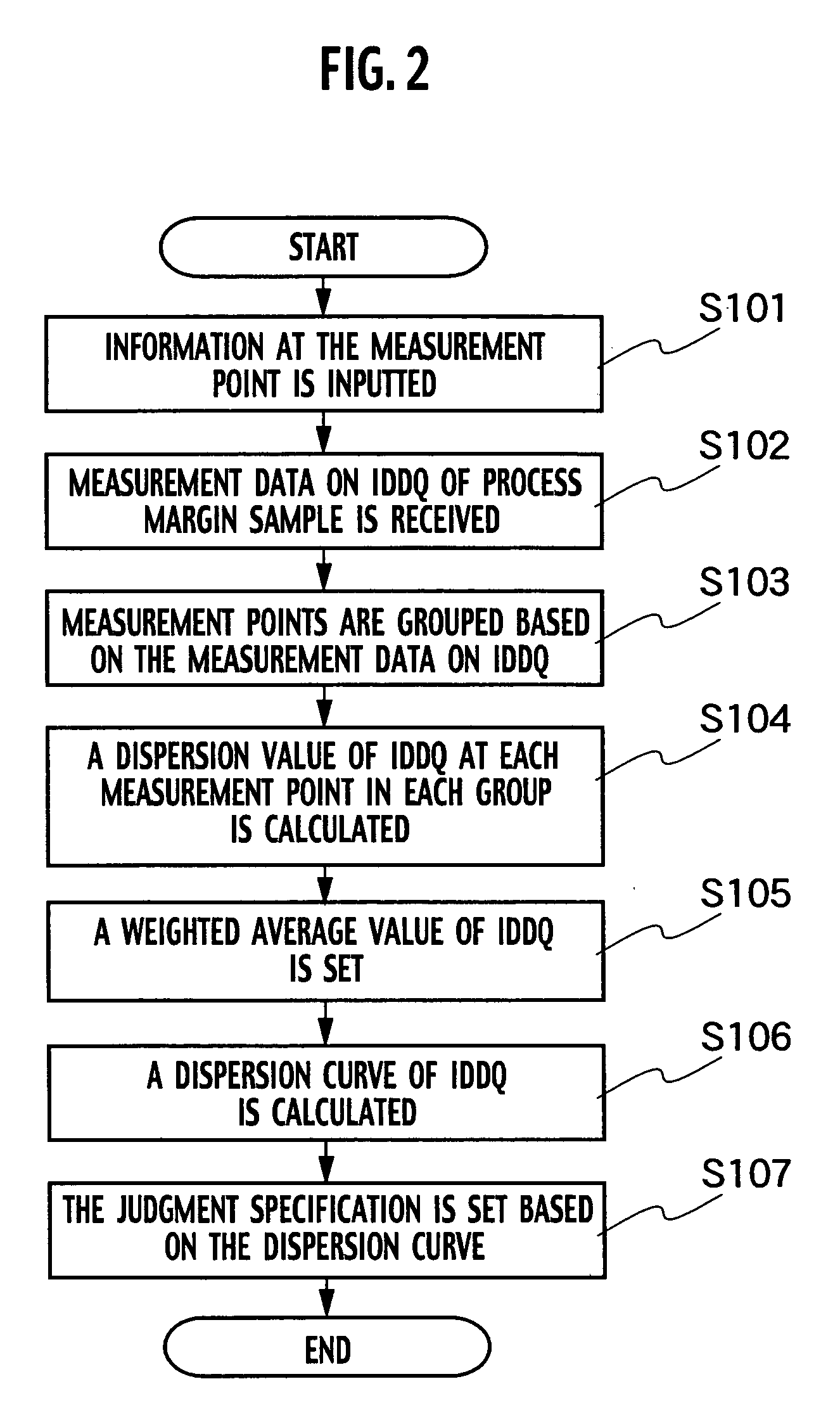
A test system for an integrated circuit includes a grouping module grouping measurement points on basis of values of the quiescent supply current and setting measurement point groups; an average value setting module setting a weighted average value minimizes the sum of dispersion of the quiescent supply current; a calculating module calculating a maximum estimated value of dispersion of the quiescent supply current on the basis of the weighted average value; and a judgment module judging whether the integrated circuit passes or fails the judgment specification.

Description

CROSS REFERENCE TO RELATED APPLICATIONS[0001]This application is based upon and claims the benefit of priority from prior Japanese Patent Application P2003-371046 filed on Oct. 30, 2003; the entire contents of which are incorporated by reference herein.BACKGROUND OF THE INVENTION[0002]1. Field of the Invention[0003]The present invention relates to a system, a method and a program for testing an integrated circuit, particularly for a complementary metal oxide semiconductor (CMOS) circuit.[0004]2. Description of the Related Art[0005]A CMOS circuit designed in such a way that no directs current path exists when there is no defect. Therefore, after an input is determined, only a minute amount of off-leakage current flows at a steady state. Therefore, a CMOS integrated circuit with a defective or faulty part causing an abnormal leakage current can be easily distinguished from a defect-free or fault-free one and rejected by measuring the power supply current values. Utilizing the phenomen...

Claims


Application Information

Patent Timeline
Patent Type & Authority Patents(United States)
IPC IPC(8): G06F19/00G01R31/26G01R31/30H01L21/66
CPCG01R31/3008
Inventor NOZUYAMA, YASUYUKISHIDOU, MAHITO
Owner KK TOSHIBA
Learn More