Method and apparatus for determining weight of moving mailpieces

a technology of moving objects and weights, applied in the field of mailpiece processing, can solve the problems of limiting the speed of a mail processing system, consuming a huge amount of human and financial resources, and the mechanical scale for weighting moving objects is highly susceptible to vibration effects,

Active Publication Date: 2006-08-22
DMT SOLUTIONS GLOBAL CORP
View PDF2 Cites 98 Cited by
  • Summary
  • Abstract
  • Description
  • Claims
  • Application Information

AI Technical Summary

Problems solved by technology

The processing and handling of mailpieces consumes an enormous amount of human and financial resources.
At such a high processing speed, the device within the mail handling system for weighing the mailpieces has a relatively short time period in which to perform its function.
It is well known that a mechanical scale for weighting moving objects is highly susceptible to vibration effects, aerodynamic uplift / down-force of an airfoil in horizontal motion, and other environmental factors that introduce spurious noise into the measurement.
Such time delay limits the speed of a mail processing system.

Method used


Image

  • Method and apparatus for determining weight of moving mailpieces
  • Method and apparatus for determining weight of moving mailpieces
  • Method and apparatus for determining weight of moving mailpieces

Examples


second embodiment

of the Invention

[0045]The second embodiment of the invention is shown in FIG. 3. The force imparting device 120 comprises a barrier object such as a lever 320 that is pivotally fastened at one end and is angualarly displaceable by the impact of the mailpiece at the another end. The mailpiece is traveling at a predetermined velocity V1.on a transport means 360 when entering the force imparting device 120. The mailpiece transfers some of its kinetic energy to the lever 320 upon the impact, and the lever is displaced by an angle Δθ before returning to its original position. The displacement angle Δθ is measurable by the measuring means 140.

[0046]The displacement angle Δθ is proportional to inertial mass m of the mailpiece and one can apply equation (7) and using a calibration curve of known masses to derive the mass.

[0047]Preferably, the lever comprises an elongated portion and a wide flat plate mounted at the end of the elongated portion. This is to spread the impact footprint such th...

first embodiment

Modification to the Invention

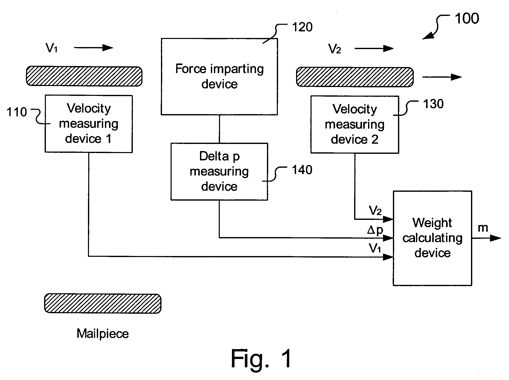
[0052]The first embodiment shown in FIG. 2 can be modified as shown in FIG. 7. In FIG. 7, the force imparting device 120 comprises a first roller 224, a second roller 222 and a calibrated dual-mode servomotor 226 that is coupled with the first roller 224. The first roller 224 and the second roller 222 have substantially the same dimensions and characteristics. The rollers are preferably urged toward each other so as to automatically accommodate mailpieces of different thickness. Whenever there is no mailpiece present in the gap, the first roller 224 is rotating at a constant angular velocity, powered by the servomotor 226. The servomotor 226 is capable of producing a voltage or current signal to a voltage (or current)-to-frequency converter 228 that is in communication with the Δp measuring device 140. Also, the servomotor 226 is in communication with a photocell trigger 230.

[0053]A mailpiece having a first velocity V1 is pinched between the two rollers ...


PUM


Abstract

The invention pertains to a mailpiece weight measuring apparatus for use with a high speed automatic mailpiece processing system. The weight measuring apparatus measures the inertial mass of the mailpiece as the weight equivalent. The apparatus includes a device for determining a first velocity of a mailpiece, a device for imparting a force to the mailpiece in a direction co-linear with the first velocity so that the mailpiece exits said force impacting device at a second velocity, a device for determining the second velocity of the mailpiece, a device for determining a change in a parameter proportional to the force imparted on the mailpiece, and a device for determining the weight of the mailpiece based upon the determined first velocity, second velocity and change in the parameter.

Description

BACKGROUND OF THE INVENTION[0001]The present invention generally pertains to mailpiece processing. More specifically, the present invention relates to determining the weight of the mailpieces in automated mail handling equipment.BACKGROUND ART[0002]The processing and handling of mailpieces consumes an enormous amount of human and financial resources. For many businesses, various pieces of mail generated by a plurality of sources need to be addressed, collected, sorted, weighted and franked as part of the outgoing mail process.[0003]Automated mail handling equipment is known in the art. Mailing systems such as the Pitney Bowes DM1000™ can process uniform, single weight mailpieces at speeds up to 260 pieces per minute and non-uniform, mixed-weight mailpieces at speeds up to 130 pieces per minute. In such a system, each mailpiece is weighed and postage is calculated and imprinted onto the envelope in a single operation.[0004]At such a high processing speed, the device within the mail h...

Claims


Application Information

Patent Timeline
Patent Type & Authority Patents(United States)
IPC IPC(8): G01G7/00G01G17/00G01G19/00G01G9/00G01G11/00
CPCG01G19/005G01G19/035G07B17/00661G01G19/4148G07B2017/00701
Inventor ONG, HENSON C.
Owner DMT SOLUTIONS GLOBAL CORP
Why Eureka
Try Eureka