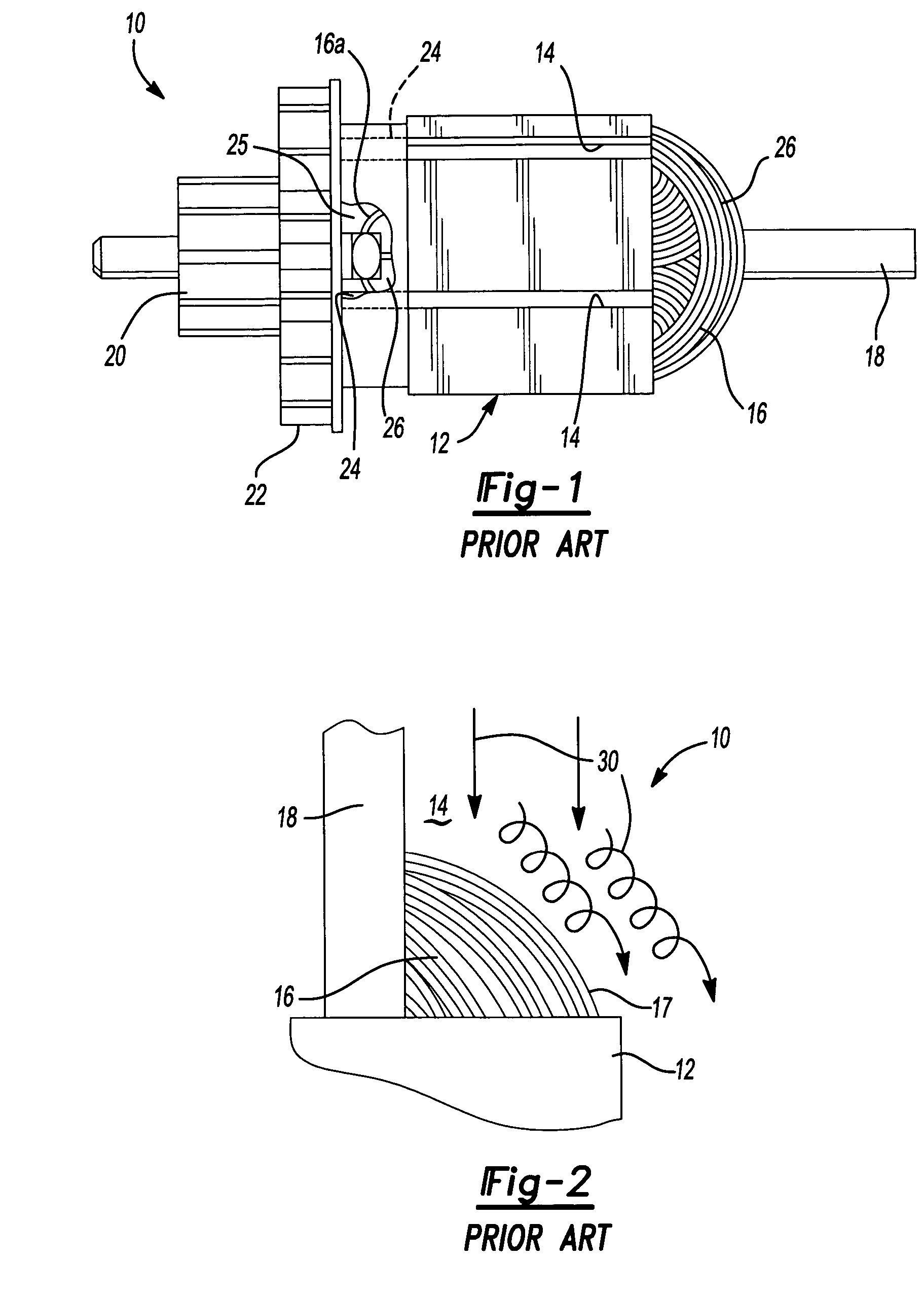
The process of applying the
trickle resin is a somewhat difficult process to manage to obtain consistent results.
It also has a number of drawbacks, not the least of which is the cost and difficulty of performing it with reliable, consistent results.
Initially, the
trickle process requires the use of a relatively large and expensive oven to carefully preheat the partially assembled armatures to relatively precise temperatures before the
trickle resin can be applied.
It has proven to be extremely difficult to achieve consistent, complete flow of the trickle resin through the slots in the lamination stack.
As such, it is difficult to achieve good flow inbetween the magnet wires with the trickle resin.
Further complicating the manufacturing process is that the trickle resin typically has a short
shelf life, and therefore must be used within a relatively short period of time.
This serves to further increase the manufacturing cost and complexity of the armature.
Still another drawback with the trickle process is the relatively high number of armatures which are often rejected because of problems encountered during the process of applying the trickle resin to an otherwise properly constructed armature.
Such problems can include
contamination of the
commutator of the armature by the trickle resin during the application process, as well as uneven flow of the trickle resin if the pump supplying the resin becomes momentarily clogged.
Accordingly, the difficulty in controlling the trickle resin application process produces a relatively large
scrap rate which further adds to the manufacturing cost of electric motors.
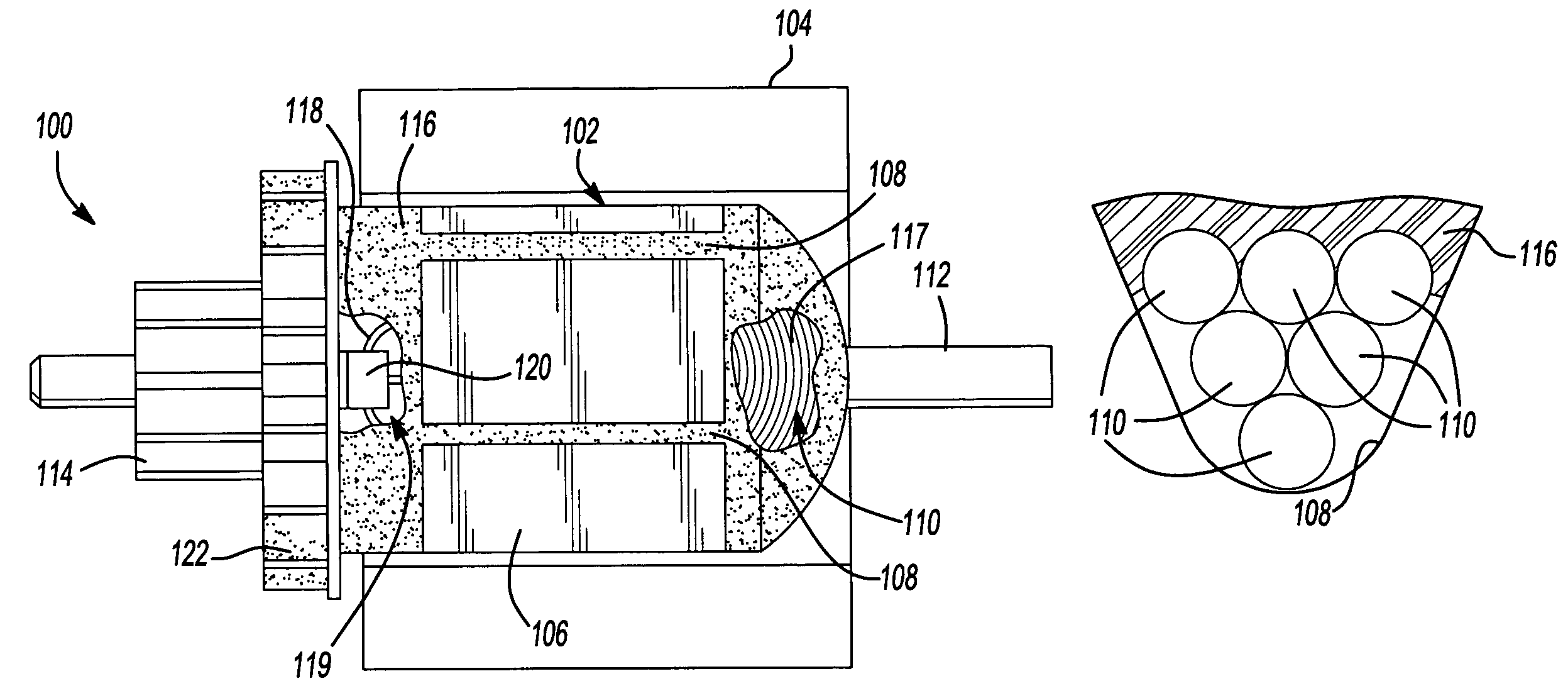
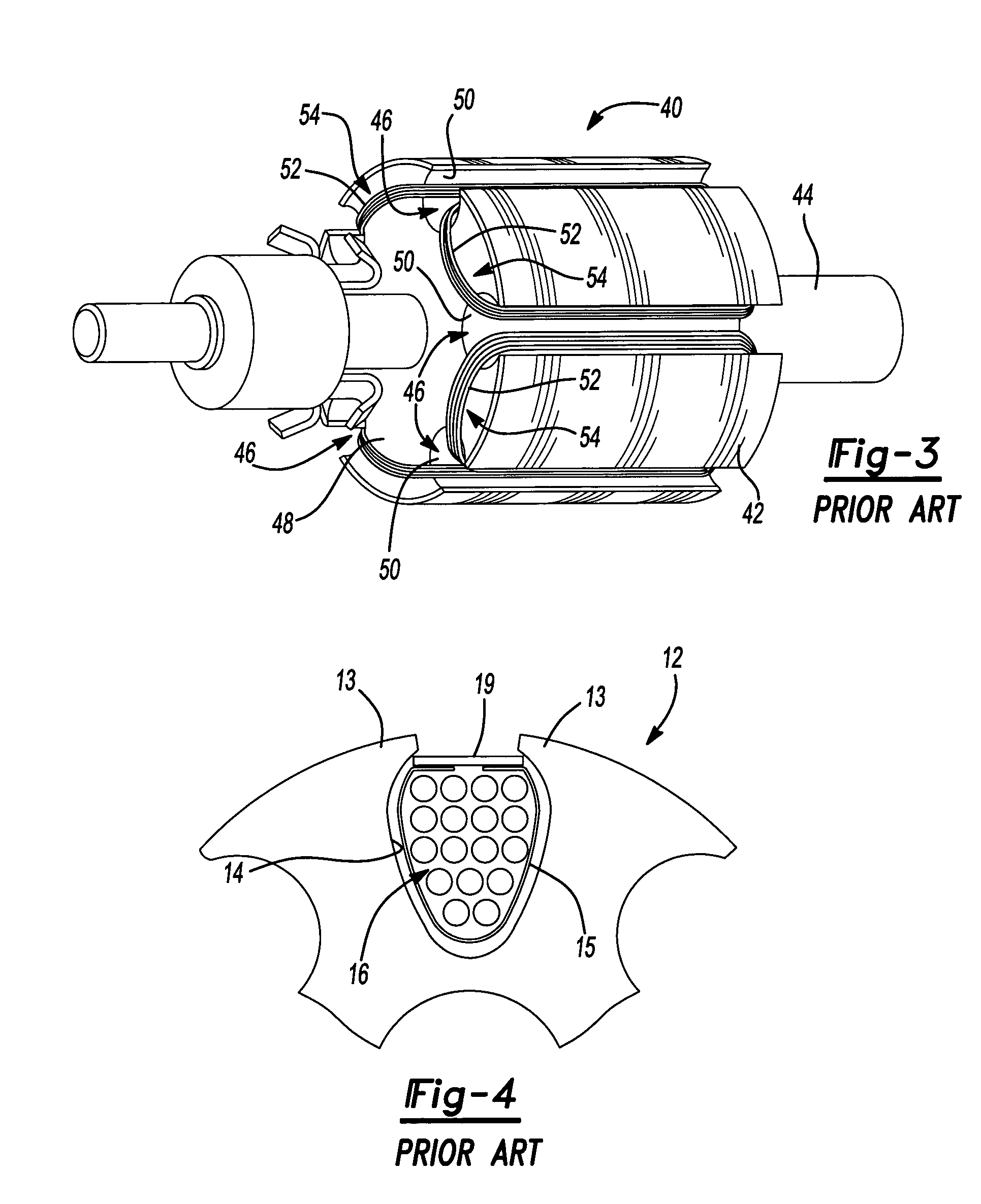
This can result in problems in dissipating the heat generated in the coils 54 during the operation of the motor in which armature 40 is used.
First, the planes in which the material are removed are located within the length of the lamination stack and thus are relatively distant from the bearing planes where the imbalance forces are transmitted to the rest of the product.
Second, removal of material from the motor's active iron core (lamination stack) has a negative effect on performance, particularly,
torque ripple.
Third, balancing by removing material from the surface of the lamination stack requires that the tooth tops of the lamination stack be thicker than needed for spreading
magnetic flux.
This non-homogeneity presents a more difficult computation to the dynamic
balancing machine that must decide how much material to remove and where to remove it from.
Consequently, the
dynamic balance machines often must make repetitive corrective passes during which even more iron is removed from the lamination stack, further reducing performance.
Such prior art coil stays have certain undesirable characteristics.
Second, the poor
thermal conductivity of the coil stay material limits the amount of heat that can be transferred to the surface of lamination stack 12.
However, using a larger size
magnet wire to wind the magnet wires would typically require larger slots to accommodate the required number of turns of the larger size
magnet wire, which in turn would require a larger lamination stack.

