Yield monitor for forage crops

Inactive Publication Date: 2006-08-29
WISCONSIN ALUMNI RES FOUND
View PDF22 Cites 7 Cited by
  • Summary
  • Abstract
  • Description
  • Claims
  • Application Information

AI Technical Summary

Benefits of technology

[0026]In accordance with yet another aspect of the invention, a computer-implemented method for providing a yield feedback in a forage processing machinery is provided. The method comprises the steps of determining in a first computer a forage mass flow rate through the forage processing machinery, receiving in the first computer a groundspeed measurement of a fora

Problems solved by technology

Therefore, although much progress has been made in yield monitored device

Method used


Image

  • Yield monitor for forage crops
  • Yield monitor for forage crops
  • Yield monitor for forage crops

Examples


first embodiment

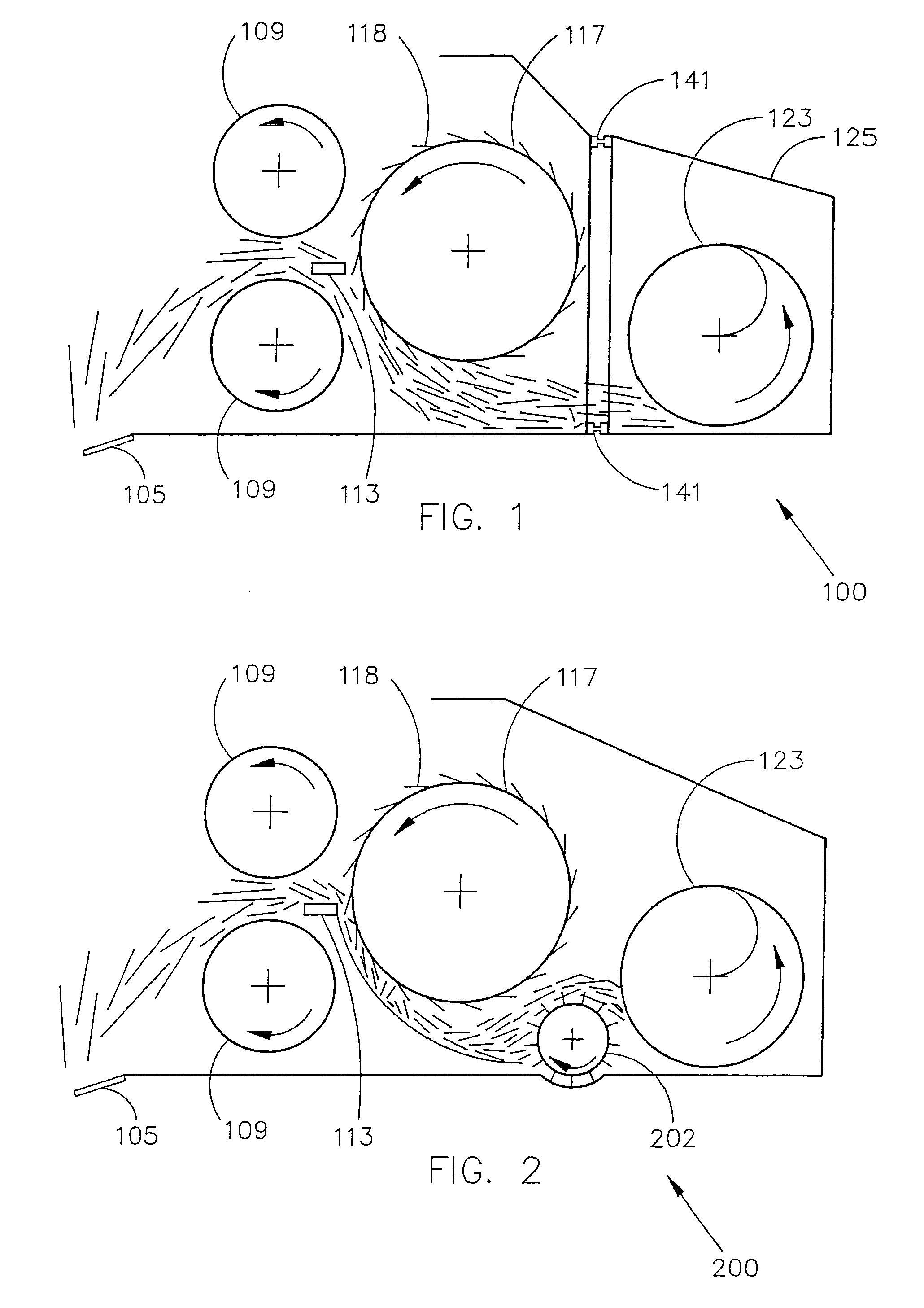
[0080]FIG. 6 shows a yield monitor for a forage processing machinery having a pair of rollers, such as, for example, a roller type mower conditioner. The roller type mower conditioner includes rollers 606 that rotate, with the forage passing between the rollers 606. The rollers 606 may include flutes 609, which serve to break or crimp the forage stems. Alternatively, the rollers 606 may be smooth, and the forage stems are crushed or smashed as the forage passes between the rollers 606.

[0081]Many forage crops are cut and field wilted prior to harvest. The mower conditioner combines the cutting function and a conditioning function, and is typically used to speed drying of a cut forage. If forage is harvested when it contains a lot of moisture, it may rot or mold. Because forage stems and leaves dry at different rates, cut forage must lay in the field for a long period of time to dry. This makes the drying crop vulnerable to other problems, such as rain, humidity, or runoff. The functi...

second embodiment

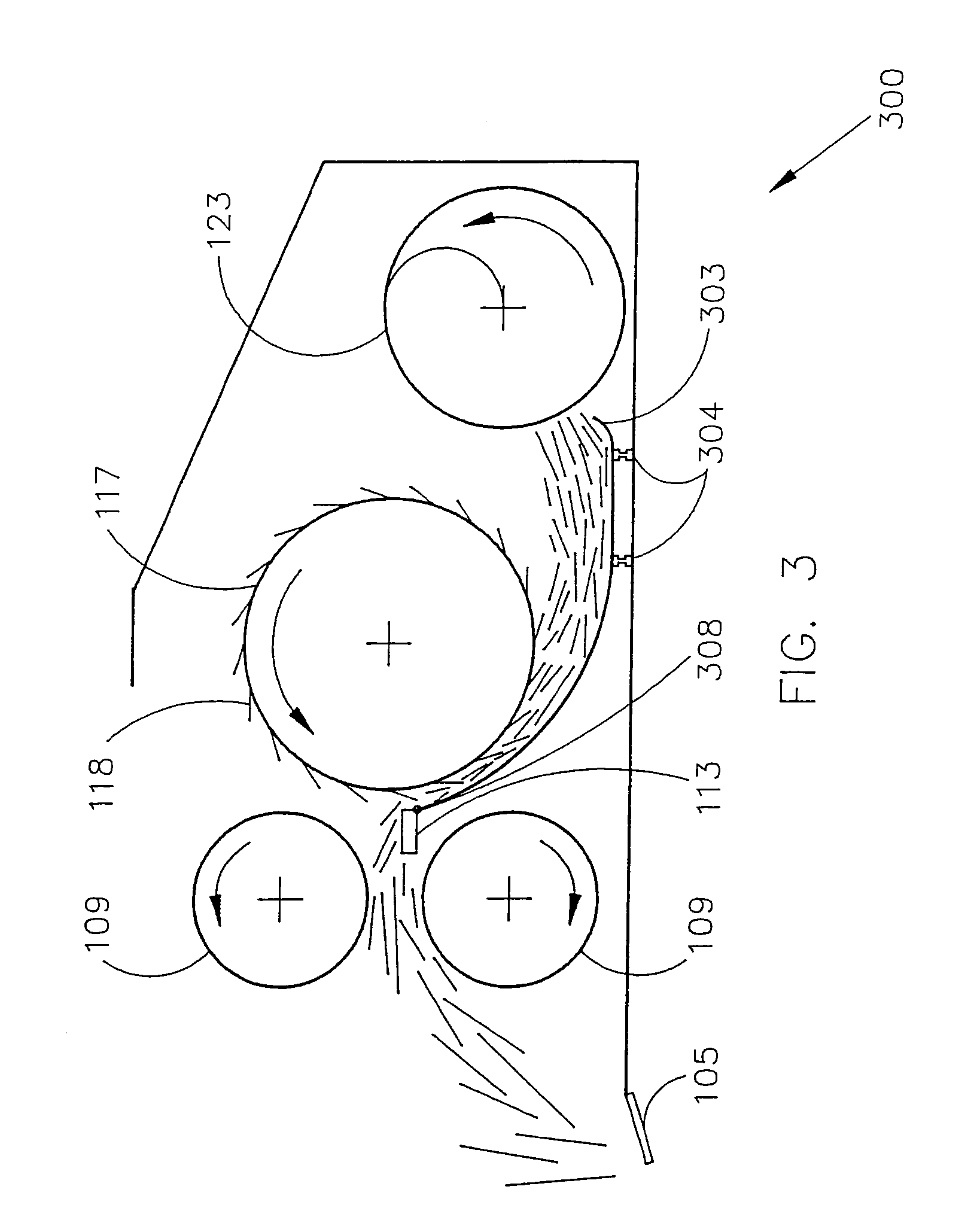
[0090]FIG. 7 shows a yield monitor for a forage processing machinery having a pair of rollers. As in the previous embodiment, the rollers 706 rotate to pass through a forage stream. In use, the rollers 706 are displaced according to the forage volume, and therefore the displacement is substantially related to the forage yield. The feed roller displacement measurement may be made through a depth sensor 716, such as, for example, an ultrasonic position transducer or linear variable differential transformer. The depth sensor 716 provides a displacement measurement that is related to a mass flow rate through the feed rollers 706.

[0091]An ultrasonic sensor offers the advantage of a displacement measurement capability without a physical link to a feed roller or a conditioner roller. In addition, an ultrasonic sensor may be added to a forage processing machinery without the need for modifications to the existing structure. The ultrasonic sensor may be merely attached to the forage processi...


PUM


Abstract

Yield monitor apparatus and method for a forage processing machinery are provided according to the invention. The yield monitor measures a forage yield by measuring a forage volume increment accumulation. In one embodiment of the invention, the yield monitor includes a volume increment accumulation measuring device generating a volume increment accumulation signal substantially related to a forage mass and a computer that receives the volume increment accumulation signal. The computer generates a yield amount based upon the accumulation signal, a forage processing machinery groundspeed, and forage processing machinery intake parameters. The yield monitor may generate a yield amount, with the yield amount capable of being stored and displayed to a forage processing machinery operator. Alternatively, the yield monitor may generate a groundspeed control signal that is used by the forage processing machinery to control a forage processing machinery groundspeed or other forage processing machinery parameters.

Description

CROSS-REFERENCE TO RELATED APPLICATION[0001]This application is a divisional application of U.S. patent application Ser. No. 10 / 208,692, filed Jul. 29, 2002, now U.S. Pat. No. 6,616,527, which is a divisional application of U.S. patent application Ser. No. 09 / 606,221, filed Jun. 29, 2000, now U.S. Pat. No. 6,431,981, which claims the benefit of U.S. Provisional Application, Ser. No. 60 / 141,799, filed Jun. 30, 1999.STATEMENT REGARDING FEDERALLY SPONSORED RESEARCH OR DEVELOPMENT[0002]This invention was made with United States government support awarded by the following agencies: USDA 98-CRHF-0-6055. The United States has certain rights in this invention.BACKGROUND OF THE INVENTION[0003]1. Field of the Invention[0004]The present invention relates generally to a yield monitor, and more particularly to a yield monitor for use with forage processing machinery.[0005]2. Description of the Background Art[0006]Modern farming has continued to evolve and change as farmers strive to increase eff...

Claims


Application Information

Patent Timeline
IPC IPC(8): A01D75/00A01D43/08A01F29/09
CPCA01F29/09A01D43/085A01D41/1271
Inventor SHINNERS, KEVIN J.BARNETT, NEIL G.SCHLESSER, WALTER M.
Owner WISCONSIN ALUMNI RES FOUND
Why Eureka
Try Eureka