Systems, methods and apparatus of an actively shielded superconducting magnet drift compensation coil

a superconducting magnet and drift compensation technology, applied in the direction of superconducting magnets/coils, instruments, magnetic bodies, etc., can solve the problems of small decay in field strength, contribute to the interpretation of field error, and decay in field strength contribute to the image produced from the magnetic field

Active Publication Date: 2006-08-29
GENERAL ELECTRIC CO
View PDF5 Cites 38 Cited by
  • Summary
  • Abstract
  • Description
  • Claims
  • Application Information

AI Technical Summary

Problems solved by technology

Unfortunately, superconducting magnets typically experience a small decay in field strength at a rate of the order of about 0.01 parts per million per hour.
Decay in the field strength contributes imprecision to the interpretation of the field, and ultimately, contributes error to the image produced from the magnetic field.
Drift of more than 1 Hz over a few minutes, therefore results in a significant loss of resolution. fMRI images are also sensitive to frequency shifts of a few Hz.
In most conventional MRI systems, the rate of decay is reduced to very low levels by manufacturing the MRI systems with high specification wire and sophisticated joints, which is expensive.
Unfortunately, this coupling renders the drift compensation coils prone to extremely high peak induced currents (e.g. ˜1000 A) during a quench of the primary coil.
For actively shielded magnets, this high current in a drift compensation coil can cause extensive magnetic field bloom which is potentially dangerous and could damage sensitive equipment in the vicinity of the magnet.
Magnetic field bloom can cause electrical medical equipment to malfunction and cardiac pacemakers in humans to malfunction.
Thus, conventional drift compensation coils can have harmful and dangerous effects that are contradictory to the goals of the healthcare settings in which they operate.
Excessive peak induced current in the drift compensation coil may also damage the drift compensation coil.
When the primary coil quenches, the drift compensation coil will rapidly accumulate current and, at some point, it will probably quench also because either it reaches the maximum current at which it can remain in a superconducting state, or an increasing Lorentz force produces a wire movement causing frictional heating.
Thus, drift compensation coils have a low normal electrical resistance and therefore can continue to accumulate current after quenching.
However, inducing a quench of the drift compensation coil at the lower induced current is difficult.
However reducing the cross sectional area of copper in the wire will also reduce the normal current carrying capacity of the wire, resulting in increased risk of quench damage.

Method used


Image

  • Systems, methods and apparatus of an actively shielded superconducting magnet drift compensation coil
  • Systems, methods and apparatus of an actively shielded superconducting magnet drift compensation coil
  • Systems, methods and apparatus of an actively shielded superconducting magnet drift compensation coil

Examples


an embodiment

Apparatus of an Embodiment

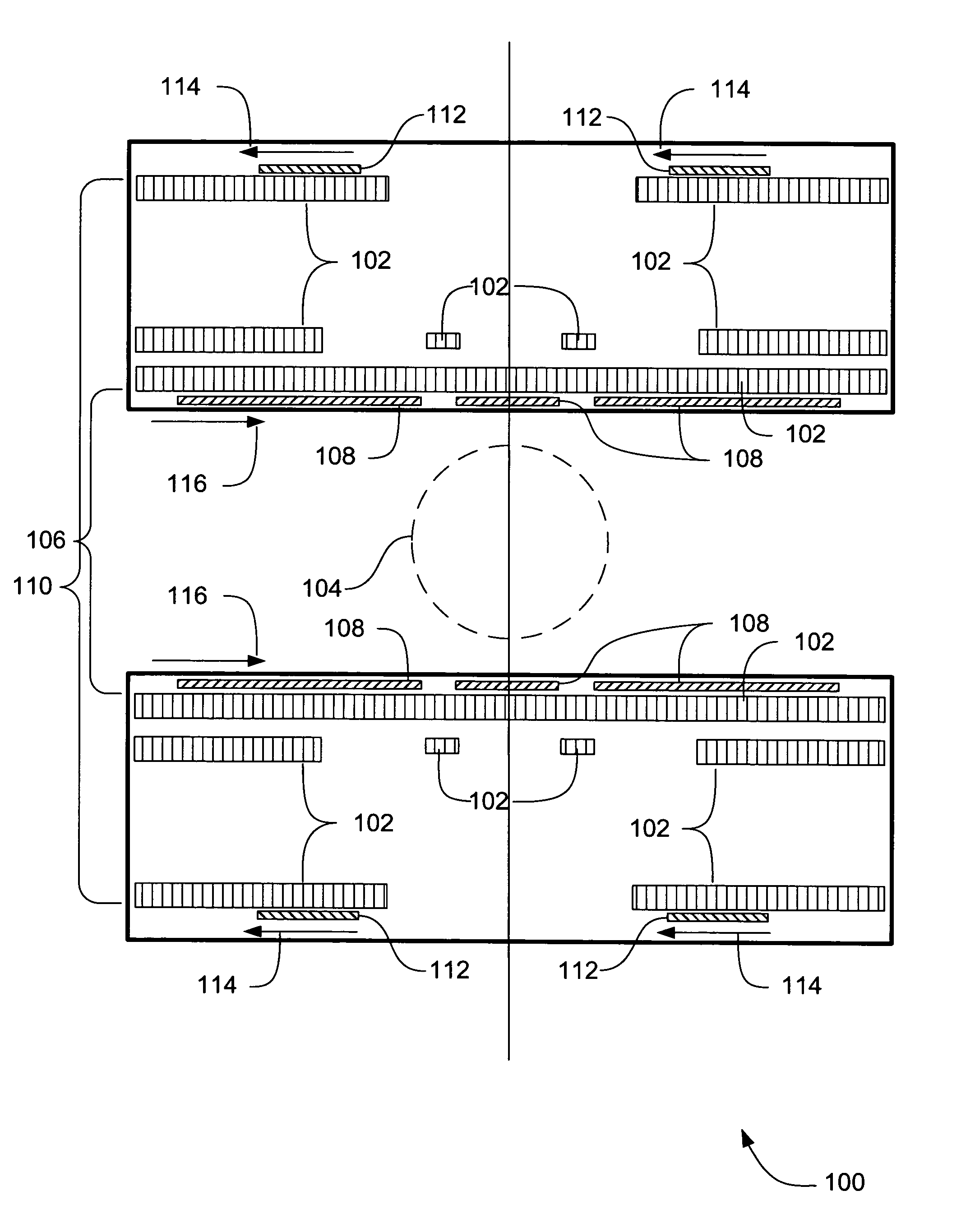
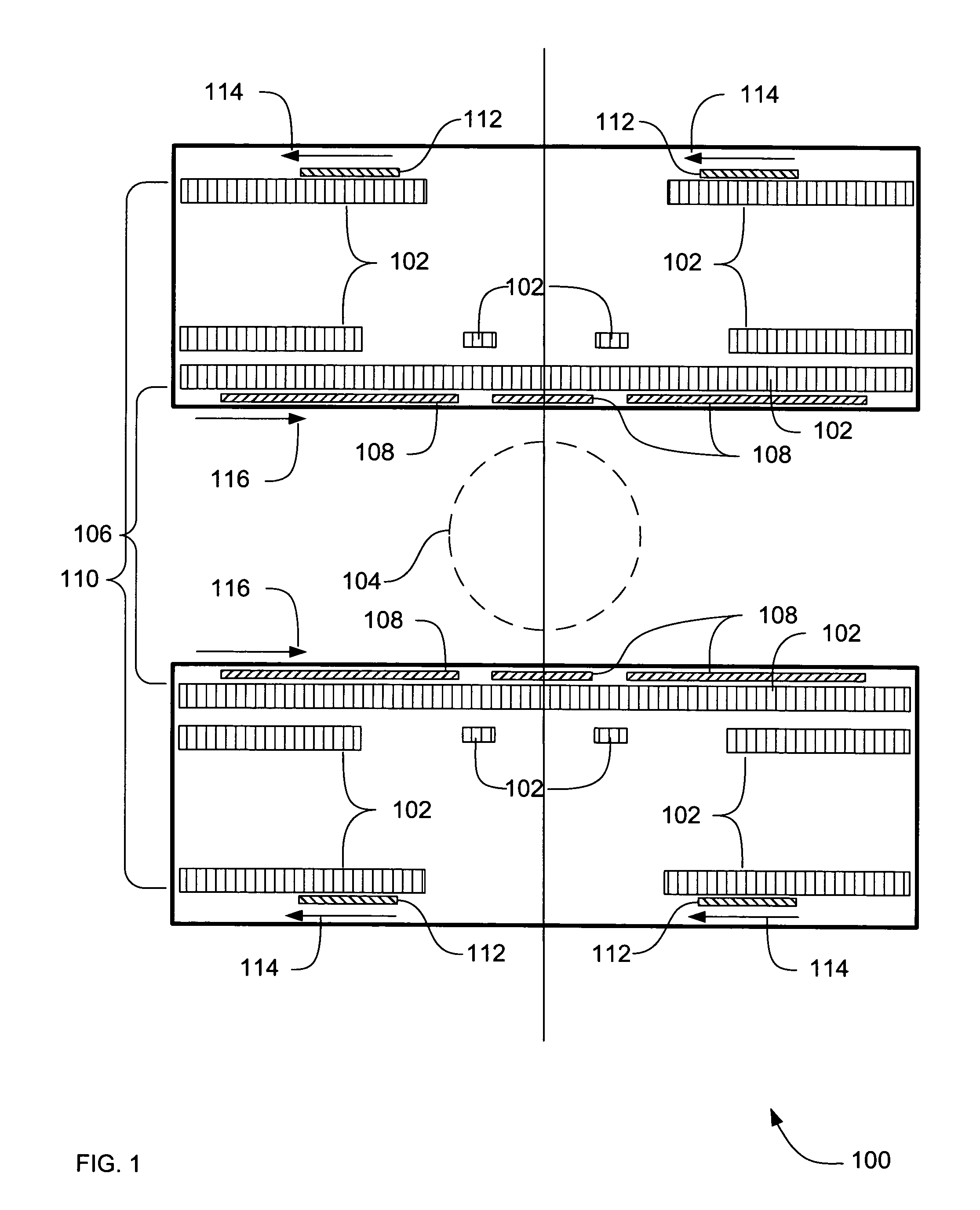
[0031]In the previous section, a system level overview of the operation of an embodiment was described. In this section, the particular apparatus of such an embodiment are described by reference to a series of diagrams.

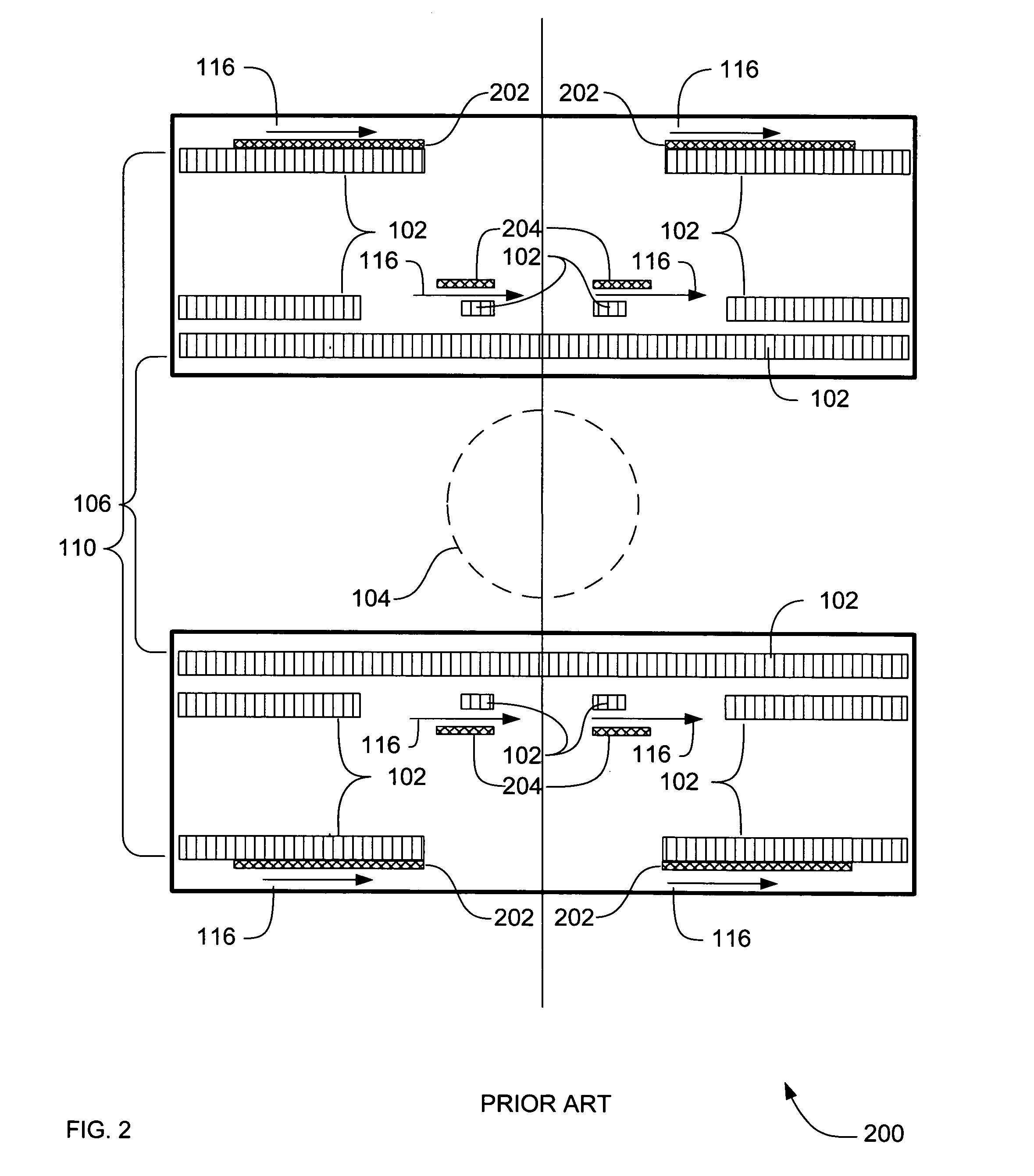
[0032]FIG. 2 is a cross section block diagram of optional prior art apparatus 200 according to an embodiment that includes a non-coupling external disturbance shield coil.

[0033]In apparatus 200, outer turns 202 of a non-coupling external disturbance coil are positioned near the outer diameter 110 of the primary coil 102. Inner turns 204 of the non-coupling external disturbance shield are positioned near the inner diameter 106 of the primary coil 102.

[0034]The non-coupling external disturbance shield coil has a majority of turns in the outer turns 202, with additional turns in the inner turns 204. The outer turns 202 and inner turns 204 are both wound in the same direction 116. The additional turns located in inner turns 204 reduce mutual indu...


PUM


Abstract

Systems, methods and apparatus are provided through which in some embodiments drift of a magnetic field of a magnetic resonance imaging (MRI) system is reduced by including a drift compensation coil which accumulates current at a rate proportional to the decay in the primary coil via its electromagnetic mutual inductance to the primary coil. In some embodiments, the drift compensation coil includes reverse turns at an outer radius, to significantly reduce any exacerbation of the fringe field during a quench of the primary coil. In further embodiments, the actively shielded drift compensation coil is complemented with a non-coupling external disturbance shield coil.

Description

FIELD OF THE INVENTION[0001]This invention relates generally to generating magnetic fields, and more particularly to modifying generated magnetic fields.BACKGROUND OF THE INVENTION[0002]Magnetic resonance imaging (MRI) systems use a magnetic field to sense the structure of an object. The structure creates perturbations and variations in the strength in the imaging volume of the magnetic field. The perturbations and variations in the strength of the magnetic field are sensed and interpreted to provide an image of the structure of the object. In many MRI systems, the magnetic field is generated by a superconducting magnet to provide a strong magnetic field. The sensing and interpreting of the magnetic field assumes a magnetic field strength of a particular amount.[0003]Unfortunately, superconducting magnets typically experience a small decay in field strength at a rate of the order of about 0.01 parts per million per hour. Field decay is also known as drift. For a preponderance of sup...

Claims


Application Information

Patent Timeline
Patent Type & Authority Patents(United States)
IPC IPC(8): G01V3/00
CPCG01R33/3815G01R33/3875G01R33/389
Inventor HOLLIS, TIMOTHY JAMES
Owner GENERAL ELECTRIC CO
Why Eureka
Try Eureka