Single focus wide-angle lens

a single-focus, wide-angle technology, applied in the field of single-focus wide-angle lenses, can solve the problems of unsatisfactory comprehensive performance of these lenses, small and lightweight size of image pickup devices using such image pickup elements, and disadvantages in productivity and cost, so as to achieve high performance and compactness, effectively using aspheric surfaces

Active Publication Date: 2006-08-29
TIANJIN OFILM OPTO ELECTRONICS CO LTD
View PDF6 Cites 16 Cited by
  • Summary
  • Abstract
  • Description
  • Claims
  • Application Information

AI Technical Summary

Benefits of technology

[0007]The present invention relates to a single focus wide-angle lens with a small number of lens components and lens elements that is capable of realizing high performance and compactness by effectively using aspheric surfaces.

Problems solved by technology

Therefore, image pickup devices using such image pickup elements now need to be small and lightweight.
However, although aspheric surfaces assist in obtaining compactness and higher performance, they are disadvantageous in terms of productivity and cost.
The single focus lenses described in Japanese Laid-Open Patent Application H10-048516 discussed above use three lens components that are lens elements and include aspheric surfaces, but the comprehensive performance of these lenses is unsatisfactory.
If the optical performance is made adequate for various purposes, the lenses are not sufficiently compact.
Generally, a lens with only three lens elements is sufficient in performance for a portable modular camera, but the performance is insufficient for a digital camera.

Method used


Image

  • Single focus wide-angle lens
  • Single focus wide-angle lens
  • Single focus wide-angle lens

Examples


embodiment 1

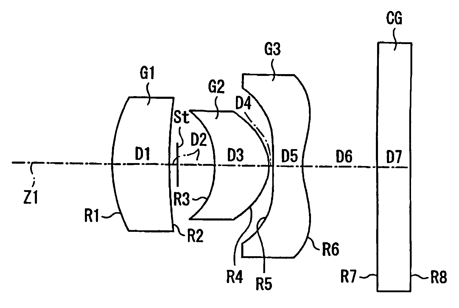
[0042]Table 1 below lists the surface number #, in order from the object side, the radius of curvature R (in mm) of each surface on the optical axis, the on-axis surface spacing D (in mm), as well as the refractive index Nd and the Abbe number νd (both at the d-line of 587.6 nm) of each optical element, including the cover glass CG but excluding the stop St, for Embodiment 1. Listed in the bottom portion of Table 1 are the paraxial focal length f, the f-number FNO, and the maximum field angle 2ω at the d-line of 587.6 nm.

[0043]

TABLE 1#RDNdνd1 3.33941.401.6583057.32 13.51661.103*−2.33081.301.5086956.04*−1.02300.105*27.35630.701.5086956.06*1.51471.827 ∞0.801.5168064.28 ∞f = 5.15 mm FNO = 4.0 2ω = 65.0°

[0044]The surfaces with a * to the right of the surface number in Table 1 are aspheric lens surfaces, and the aspheric surface shapes are expressed by Equation (A) above.

[0045]Table 2 below lists the values of the constant K and the aspheric coefficients A3–A10 used in Equation (A) above...

embodiment 2

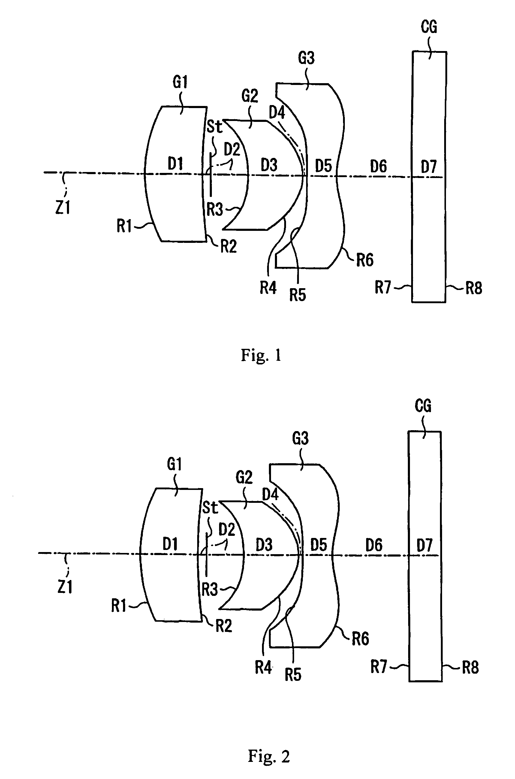
[0051]FIG. 2 shows Embodiment 2 of the present invention. Embodiment 2 is similar to Embodiment 1 and therefore only the differences between Embodiment 2 and Embodiment 1 will be explained. In this Embodiment, instead of the object side lens surface of the third lens element G3 being convex on the optical axis, it is concave on the optical axis.

[0052]Table 4 below lists the surface number #, in order from the object side, the radius of curvature R (in mm) of each surface on the optical axis, the on-axis surface spacing D (in mm), as well as the refractive index Nd and the Abbe number νd (both at the d-line of 587.6 nm) of each optical element, including the cover glass CG but excluding the stop St, for Embodiment 2. Listed in the bottom portion of Table 4 are the paraxial focal length f, the f-number FNO, and the maximum field angle 2ω at the d-line of 587.6 nm.

[0053]

TABLE 4#RDNdνd1 3.57401.401.7130053.92 13.00401.103*−2.47251.301.5086956.04*−1.02020.105*−51.78860.701.5086956.06*1.6...


PUM

PropertyMeasurementUnit
focal lengthaaaaaaaaaa
wavelengthsaaaaaaaaaa

Abstract

A single focus wide-angle lens includes, in order from the object side: a first lens component of positive refractive power, having a meniscus shape, and having a convex object-side surface; a stop; a second lens component of positive refractive power, having a meniscus shape, having at least one aspheric surface, having a concave object-side surface, and being made of plastic; and a third lens component of negative refractive power, having a meniscus or plano-concave or biconcave shape, having both surfaces of aspheric shape, having an image-side surface that is concave on the optical axis, and being made of plastic. The single focus wide-angle lens may include only three lens elements. Specified on-axis conditions are satisfied in order to reduce aberrations and to make the single focus wide-angle lens compact. Additionally, satisfying a condition related to the half-field angle at the maximum image height helps reduce aberrations.

Description

FIELD OF THE INVENTION[0001]The present invention relates to a single focus wide-angle lens that can be mounted in small information terminal equipment such as a cellular telephone with a camera and in a Personal Digital Assistant (PDA).BACKGROUND OF THE INVENTION[0002]In recent years, digital still cameras (hereinafter referred to simply as digital cameras) that enable input of picture image information, such as photographed landscapes and portraits, into a personal computer have rapidly become popular with the popularity of personal computers in households. In addition, along with advanced functions of cellular phones, camera phones that incorporate compact image pickup modules have also rapidly become popular. Furthermore, including an image pickup module in compact information terminal equipment, such as PDAs, has also become popular.[0003]In such devices that include an image pickup function, an image pickup element, such as a CCD (Charge Coupled Device) or a CMOS (Complementar...

Claims


Application Information

Patent Timeline
Patent Type & Authority Patents(United States)
IPC IPC(8): G02B9/12G02B13/04G02B3/02G02B13/00G02B1/04G02B13/06G02B13/18G02B15/14G02B15/163
CPCG02B13/0035G02B9/12G02B1/041G02B5/281G02B13/18
Inventor SATO, KENICHI
Owner TIANJIN OFILM OPTO ELECTRONICS CO LTD
Why Eureka
Try Eureka