
Geophone and method of manufacturing a geophone

Inactive Publication Date: 2006-08-29
SCHLUMBERGER TECH CORP
View PDF20 Cites 23 Cited by
  • Summary
  • Abstract
  • Description
  • Claims
  • Application Information

AI Technical Summary

Benefits of technology

[0028]Both methods of manufacturing allow the use of light and thing materials which improves the sensitivity of the resulting transducer. Also, an expensive machining step is avoided which allows dramatic cost reduction in the manufacturing of the transducer.

Problems solved by technology

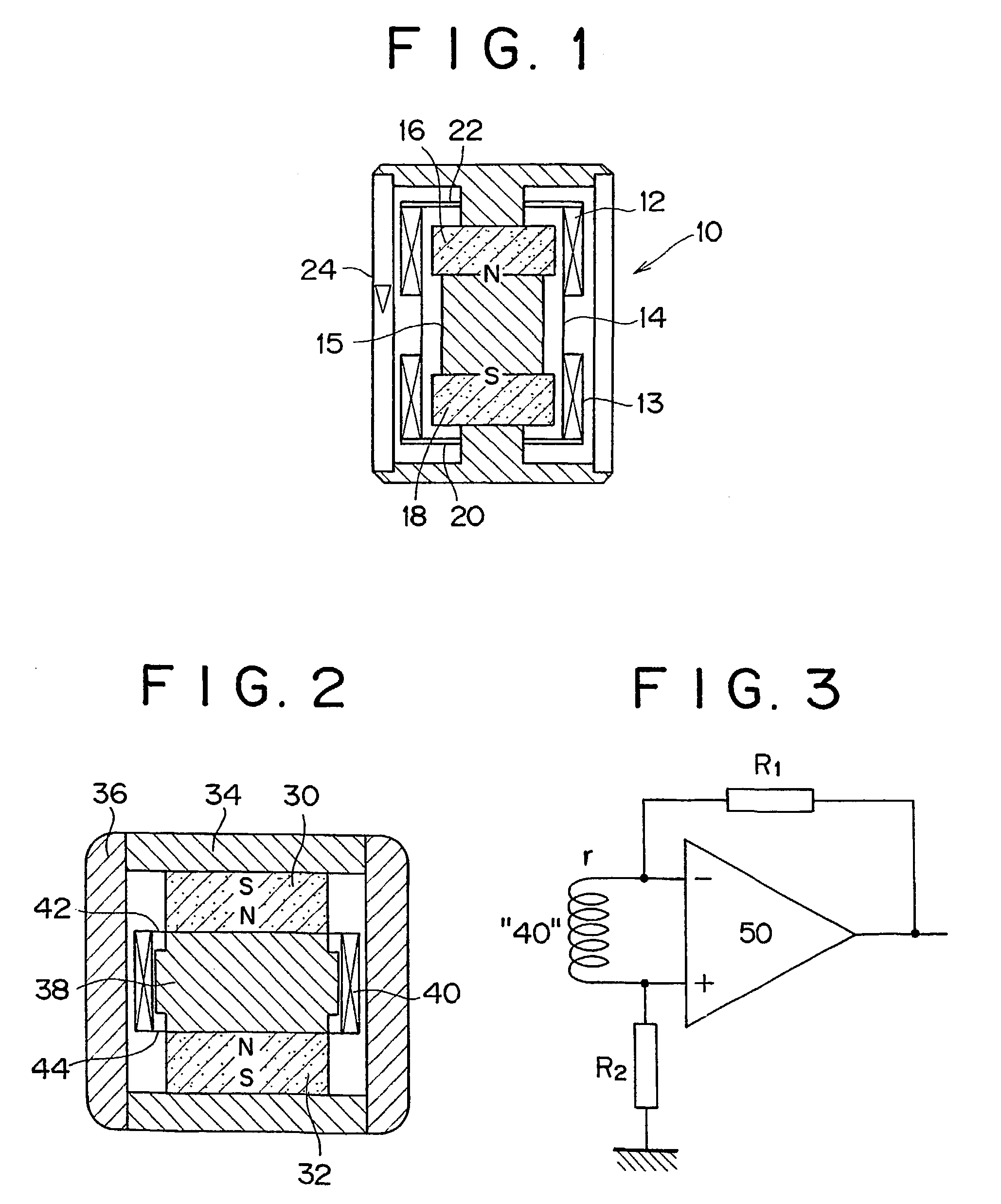
One problem encountered with this design is how to increase sensitivity without dramatically increasing the size of the sensor, especially its diameter when considering use as a borehole sensor.
While it is possible to attain a suitable size for such a sensor, the assembly cost has proved to be high.
Another problem with the prior art design of FIG. 1 is that the bobbin 14 should preferably be as light as possible.
However, in the past this bobbin has been machined from metal which has proven both expensive and difficult to achieve the small thickness desired for size and mass limitations.

Method used


Image

  • Geophone and method of manufacturing a geophone
  • Geophone and method of manufacturing a geophone
  • Geophone and method of manufacturing a geophone

Examples


Embodiment Construction

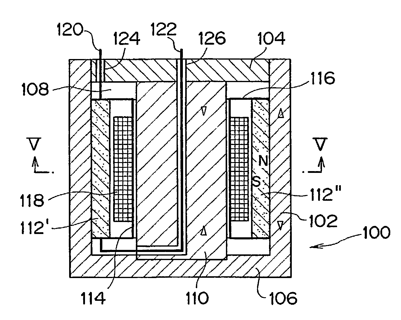
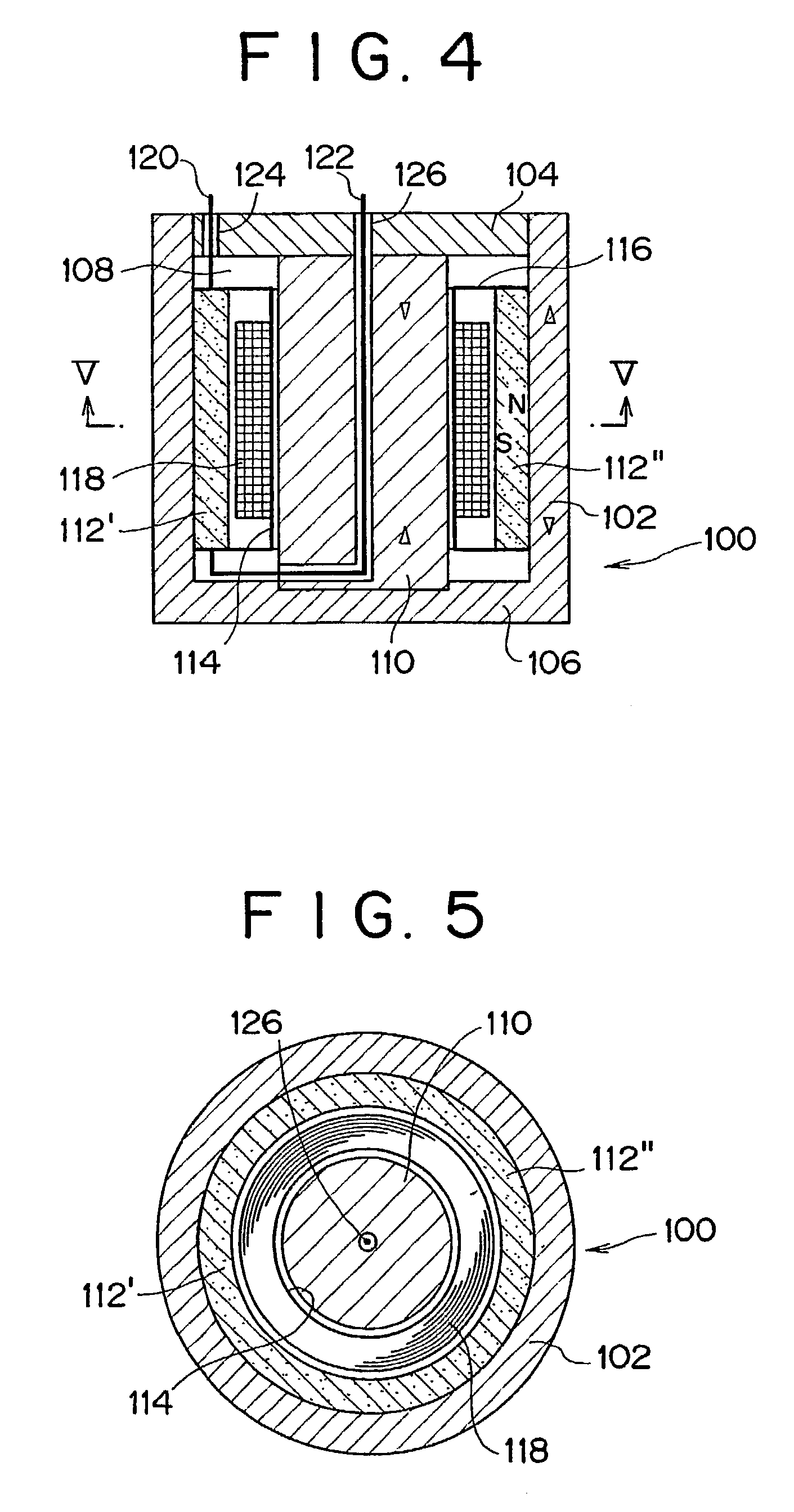
[0045]A geophone suitable for use in seismic surveying and embodying the present invention is shown in FIGS. 4 and 5. The geophone 100 comprises a hollow, tubular housing 102 formed from steel having its ends closed by steel end caps 104, 106 so as to form a cavity 108 inside the housing 102. A cylindrical steel centre pole piece 110 extends between the end caps 104, 106 through the cavity 108. In the embodiment shown in FIG. 4, one end cap 106 is integrally formed with the housing 102 and the other end cap 104 fits inside the upper part of the housing 102 to define the cavity. The pole piece 110 is formed separately from the end caps 104, 106, but is connected to them when the geophone is assembled. Various constructions of housing 102, end caps 104, 106 and pole piece 110 are shown in FIGS. 6a–d. Where an end cap 104 is integral with the housing 102 the pole piece 110 can be formed integrally with the other end cap 106 (FIGS. 6a and 6b). The end caps 104, 106 can also be formed se...


PUM


Abstract

A vibration transducer such as a geophone, comprising a central pole piece (110) with a magnet (112) and coil (118) concentrically arranged around it. The position of the magnet (112) is fixed relative to the pole piece (110) and the coil (118) is movable relative to the magnet (112). A method of manufacturing a vibration transducer is characterised in that a bobbin carrying the coils is formed from a substantially tubular body which is positioned on a mandrel and at least one coil is wound around its outer surface, the mandrel being removed from the bobbin when the coil is complete. Another method is characterised in that the coil is formed separately and the bobbin is formed from a substantially tubular body which is positioned inside the coil and expanded to contact the coil when in position.

Description

FIELD OF THE INVENTION[0001]The present invention relates to geophones, devices for sensing vibrations in earth formations. The invention may be applicable to other types of vibration transducers, either in sensing or transmitting operation.BACKGROUND AND PRIOR ART[0002]In seismic exploration, the vibrations in the earth resulting from a source of seismic energy are sensed at discrete locations by sensors and the output of the sensors used to determine the nature of the underground formations. The source of seismic energy can be natural, such as earthquakes and other tectonic activity, subsidence, volcanic activity or the like, or man-made such as acoustic noise from surface or underground operations, or from deliberate operation of seismic sources at the surface or underground. Sensors fall into two main categories; hydrophones which sense the pressure field resulting from a seismic source, or geophones which sense vibration arising from a seismic source.[0003]A prior art form of g...

Claims


Application Information

Patent Timeline
IPC IPC(8): H04R9/00G01H1/00G01H11/02G01V1/18
CPCG01V1/181Y10T137/2278
Inventor KAMATA, MASAHIRO
Owner SCHLUMBERGER TECH CORP
Learn More