
Optical isolator, attenuator and polarizer system and method for integrated optics

a technology of optical isolators and polarizers, applied in the field of optics, can solve the problems of difficult integration with other optical devices, many difficulties of prior art optical isolators,

Inactive Publication Date: 2006-08-29
SUPER TALENT ELECTRONICS
View PDF20 Cites 13 Cited by
  • Summary
  • Abstract
  • Description
  • Claims
  • Application Information

AI Technical Summary

Benefits of technology

[0008]As an option, the first branch may include an optical absorber for absorbing the reverse light that is prevented from passing into the second branch by the total reflection. In another embodiment, an optical choker may be positioned at one of the ends of one of the branches for increasing isolation.
[0009]In use, the isolation provided between the first branch and the second branch is polarization independent. As an option, a numerical aperture of one of the ends of one of the branches may be lowered for increasing the isolation. Moreover, a transmitting area of one of the branches may be decreased for increasing the isolation. Still yet, an optical choker may be positioned at one of the ends of one of the branches for increasing the isolation.
[0014]Each of the foregoing embodiments may be made of a very simple structure and have numerous optional features: ruggedness, superb thermal and environmental properties, premium stability and reliability, and excellent optical performance that are independent of polarization. Moreover, they may be easily integrated with other optical and opto-electronic devices. Each of them may be built with one or a combination of the waveguide, optical fiber, micro-optic, and photonic crystal technologies.

Problems solved by technology

Unfortunately, such prior art optical isolator exhibits many difficulties.
Not only is its function polarization dependent, but it is also difficult to be integrated with other optical devices.

Method used


Image

  • Optical isolator, attenuator and polarizer system and method for integrated optics
  • Optical isolator, attenuator and polarizer system and method for integrated optics
  • Optical isolator, attenuator and polarizer system and method for integrated optics

Examples

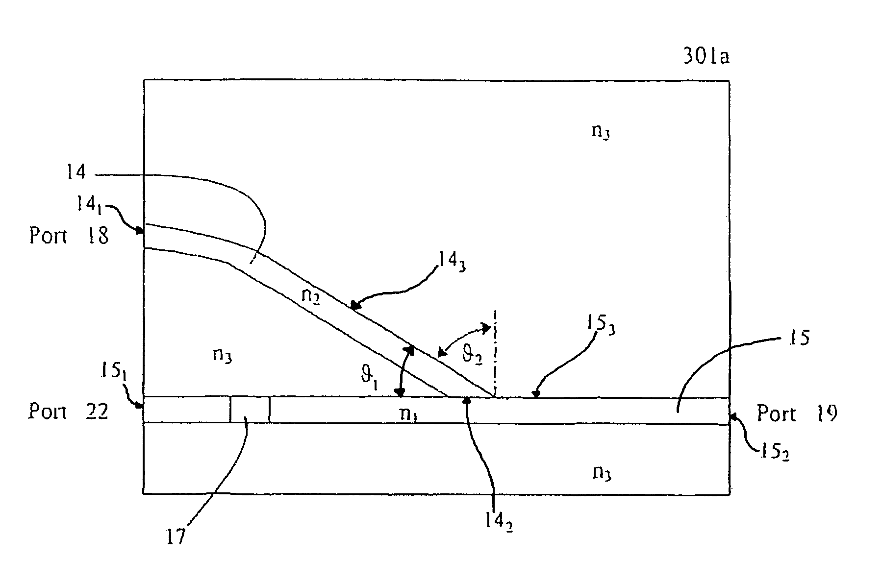
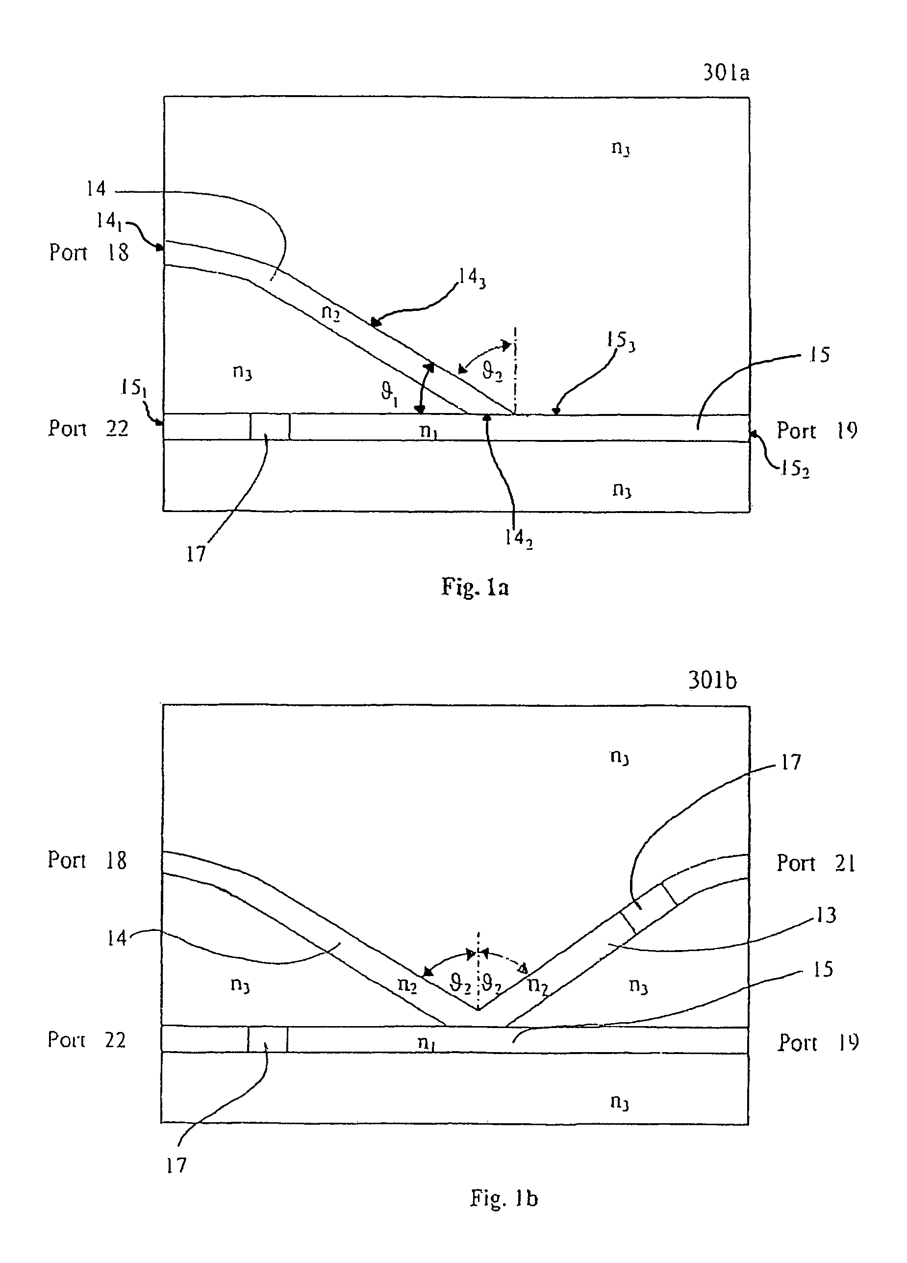
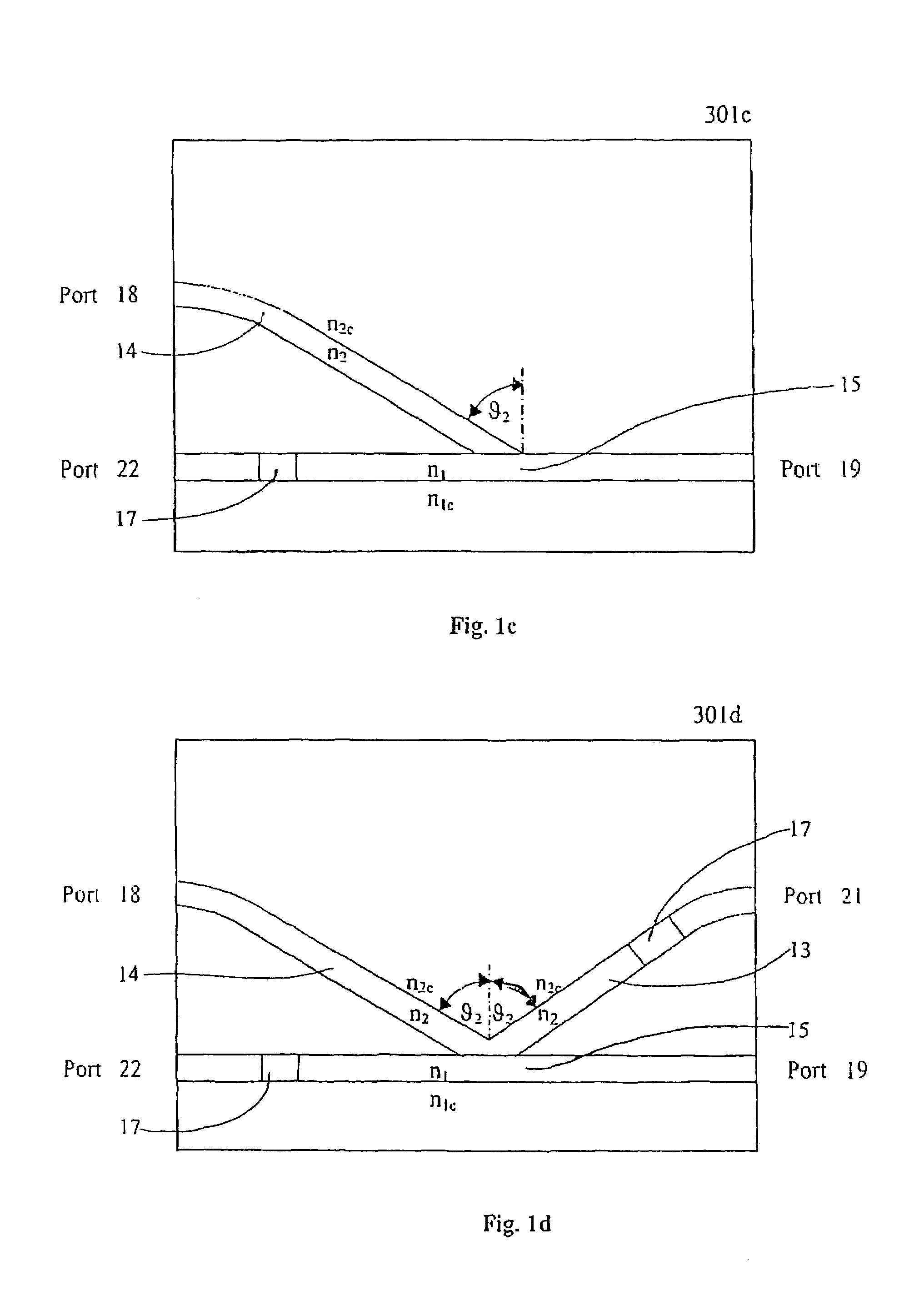

example 1

[0029]Case 1)

[0030]For FIGS. 1a and 1b: given the refraction indexes n1=1.465, n2=1.460, n3=1.455 and θ2=85.30°, then the calculated insertion loss is ˜0.13 dB with ILp=0.129 dB and ILs=0.133 dB. The polarization dependent loss (i.e. ILs−ILp) is ˜0.004 dB and the isolation is ˜9 dB.

[0031]Case 2)

[0032]For FIGS. 1c and 1d: given the refractive indexes n1=1.465, n1c=1.460, n2=1.4625, n2c=1.4575 and θ2=86.70°, then the calculated insertion loss is ˜0.13 dB with ILp=0.133 dB and ILs=0.136 dB. The polarization dependent loss is ˜0.003 dB while the isolation is also ˜9 dB.

[0033]Thus, the isolation is polarization independent (ILp≈ILs). However, the isolation of ˜9 dB is below expectation. In Case 1 of Example 1 above, although with ideally parallel incident light, the numerical aperture of the output light NA(n1, n3) is 0.171 at the output port 19 while the other numerical apertures are: NA(n2, n3)=0.121, NA(n1, n2)=0.121. Since NA (n1, n3) is greater than NA (n1, n2), a portion of the rev...

example 2

[0036]For FIG. 1g: given the refraction indexes n1=1.500, n1c=1.4958, n2=1.450 n2c=1.4457, θ2=85° and θ1=76°, the calculated insertion loss are ILp=1.24 dB and ILs=1.39 dB. The polarization dependent loss is ˜0.15 dB, the numerical aperture of the output port 19 is low and thus the isolation greatly increases to ˜12 dB.

[0037]Another way of improving isolation for 301a, 301b, 301c, 301d, 301e and 301f is to decrease the transmitting area of the reverse light from branch 15 to branch 14. If it is reduced to one half, the isolation increases by 3 dB, and by 6 dB if it is reduced to one fourth. And if all the reverse light were reflected at the junction of branches 15 and 14, then the isolation becomes perfect. Therefore, one may add an optical choker 1 to port 18, 19, as shown in FIGS. 1e, 1f and 1h. The optical choker 1 serves two purposes: (1) it lowers the numerical aperture NA, for example from 0.171 to 0.1 or even 0.01 (2) it converges the light to the center part of branches 14 a...

example 3

[0039]In the context of Example 1, if the input light numerical aperture NA was 0.12 and θ2=85°, the attenuation of both the p- and s-polarization are ≈4.3 dB and their difference is almost zero (0.009 dB).

[0040]Therefore, the attenuation is polarization independent. Calculations indicate that the smaller the angle θ2, the larger the attenuation. The attenuation can be varied with the changing incident angle θ2. Thus, a variable optical attenuator is also feasible.

[0041]Optical isolator 301a, 301b, 301c, 301d, 301e, 301f, 301g and 301h, based on the total reflection principle, have a very simple structure and result in numerous improvements: its ruggedness, its superior thermal and environmental properties, its exceptional stability and reliability, and its excellent polarization independent optical performance. Moreover, it is easily integrated with other optical and opto-electronic devices. These qualities make it suitable to construct other optical devices such as a coupler, inse...


PUM


Abstract

An optical system and associated method are provided. Included is a first branch capable of allowing light to pass therethrough in a forward direction and a reverse direction. The first branch includes a first medium with a first refractive index (n1), and a first end and a second end. Also included is a second branch capable of allowing light to pass therethrough in the forward direction. The second branch includes a second medium with a second refractive index (n2, with n2<n1), and a first end and a second end. The second end of the second branch is further coupled to the first branch to form an angle (θ2). In use, θ1≦sin−1(n2 / n1) in order to prevent the light passing through the first branch in the reverse direction from passing into the second branch, where θ1 is the incident angle of the light passing in the reverse direction from the first branch to the second branch.

Description

FIELD AND BACKGROUND OF THE INVENTION[0001]The present invention relates to optics, and more particularly to optical isolators.BACKGROUND OF THE INVENTION[0002]An optical isolator is a 1×1 unidirectional connector. It allows light to travel along a path in one direction only but not in the reverse direction within an optical system.[0003]Optical isolators are typically employed in bulk optical systems to eliminate one of two counter-propagating electro-magnetic light waves. An optical isolator is comparable with a diode having a low electrical resistance for the forward current from its input to its output and a very high resistance for the reverse current from its output to its input. Analogous, a forward light wave, fed via the optical input port of an optical isolator to its output port, is guided with low loss, and a reverse light wave, i.e. a light wave being fed to the isolator's optical output port, is attenuated such that only a very small amount thereof leaves the isolator ...

Claims


Application Information

Patent Timeline
Patent Type & Authority Patents(United States)
IPC IPC(8): G02B6/26
CPCG02B6/125G02B6/2746G02B6/266
Inventor AU, CHICHU, TZU-YIHYIN, HAOMA, ABRAHAM C.LEE, EDWARD W.
Owner SUPER TALENT ELECTRONICS
Learn More