Eureka AIR delivers breakthrough ideas for toughest innovation challenges, trusted by R&D personnel around the world.

Apparatus and method for delaying optical signals for optical buffering and optical storage applications

Active Publication Date: 2006-08-29
F POSZAT HU
View PDF19 Cites 8 Cited by
  • Summary
  • Abstract
  • Description
  • Claims
  • Application Information

AI Technical Summary

Benefits of technology

[0070]The present invention enables generation of a delayed optical signal from an inputted optical signal. The inputted optical signal is cyclically transmitted between at least two ends of an optical medium and outputted from one of the ends of the optical medium after at least one transmission cycle via the optical medium thereby generating the delayed optical signal. Each transmission of the inputted optical signal in a direction via the optical medium is carried out over a wavelength resource that is different from a wavelength resource used in a preceding transmission of the inputted optical signal in a direction via the optical medium. Interference among repeated transmissions of the inputted optical signal via the optical medium is therefore minimized or even avoided.
[0071]Each transmission cycle delays the inputted optical signal by a delay period which is a result of a division of twice the length of the optical medium by the speed of light in the optical medium. As the number of transmission cycles increases, an increased delay of the inputted optical signal may be obtained. Dispersion compensation and amplification of the inputted optical signal while traversing the optical medium may be employed to enable multiple transmission cycles without signal distortion and degradation.

Problems solved by technology

As the number of transmission cycles increases, an increased delay of the inputted optical signal may be obtained.

Method used


Image

  • Apparatus and method for delaying optical signals for optical buffering and optical storage applications
  • Apparatus and method for delaying optical signals for optical buffering and optical storage applications
  • Apparatus and method for delaying optical signals for optical buffering and optical storage applications

Examples


Embodiment Construction

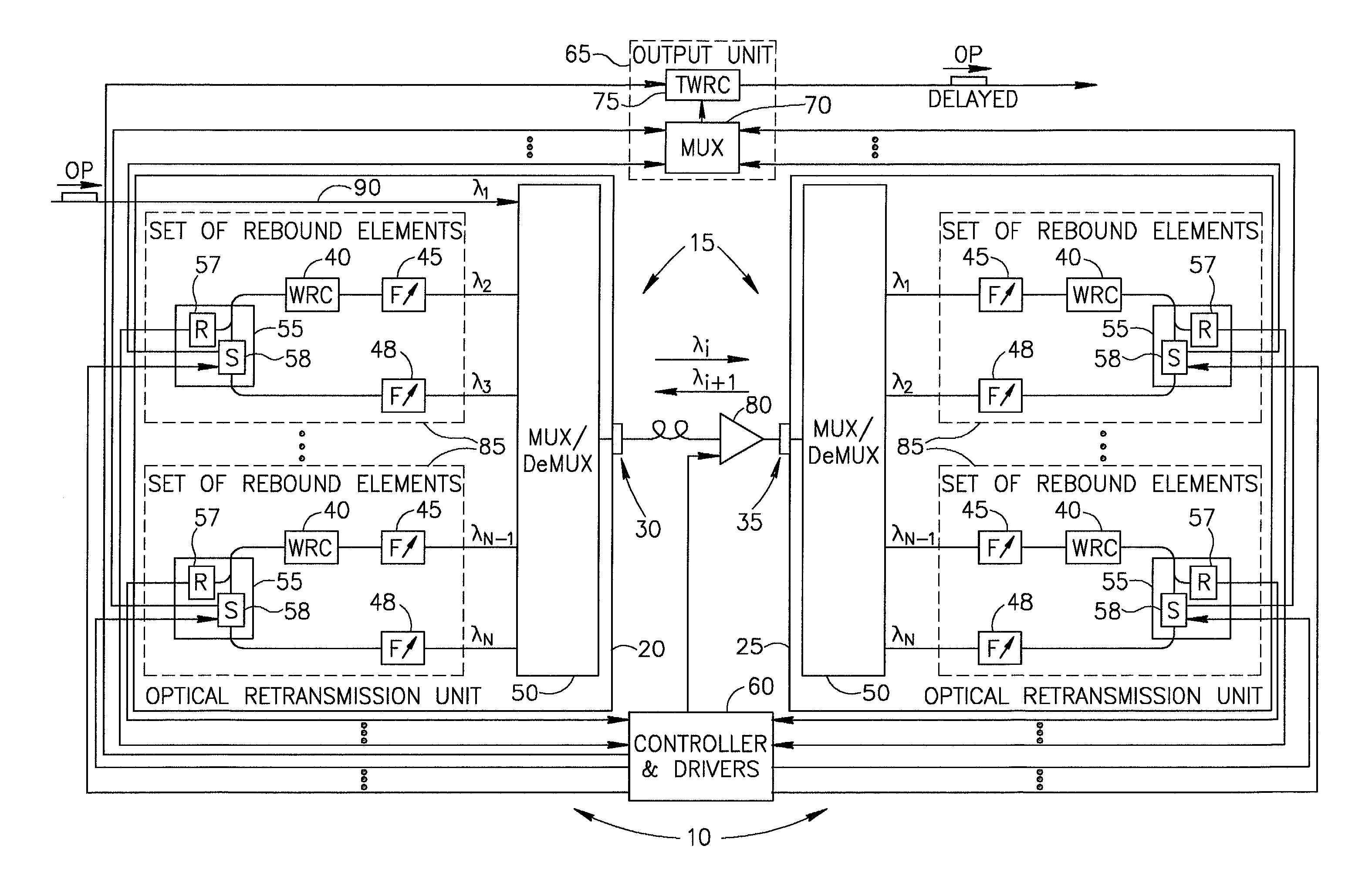
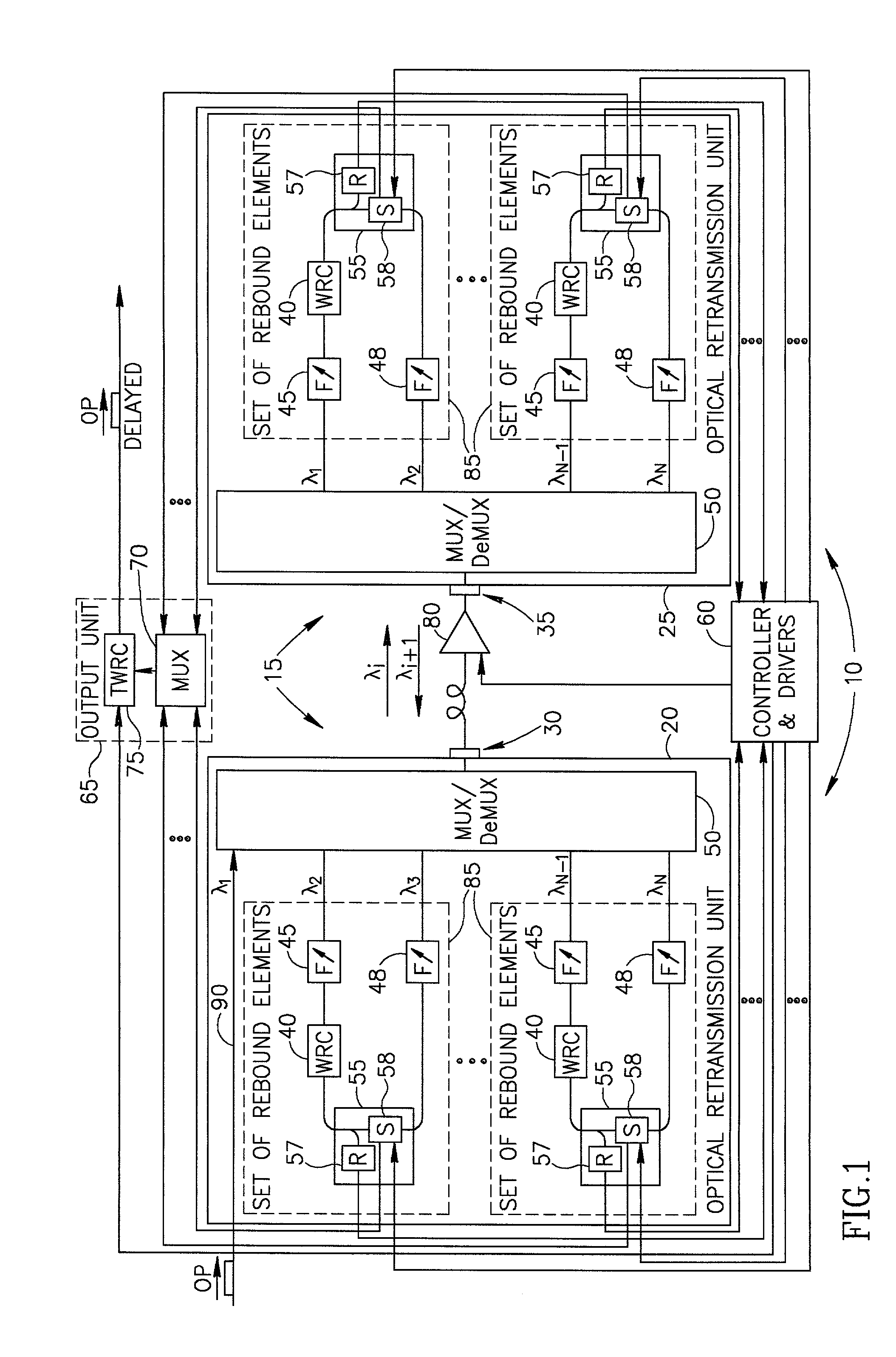
[0100]Reference is now made to FIG. 1 which is a simplified block diagram illustration of a preferred implementation of apparatus 10 for optically delaying an optical signal OP, the apparatus 10 being constructed and operative in accordance with a preferred embodiment of the present invention. As described hereinafter, the apparatus 10 preferably enables, either independently or under control of an external processing unit (not shown), to controllably delay the optical signal OP and to enable optical buffering and optical storage of the optical signal OP.

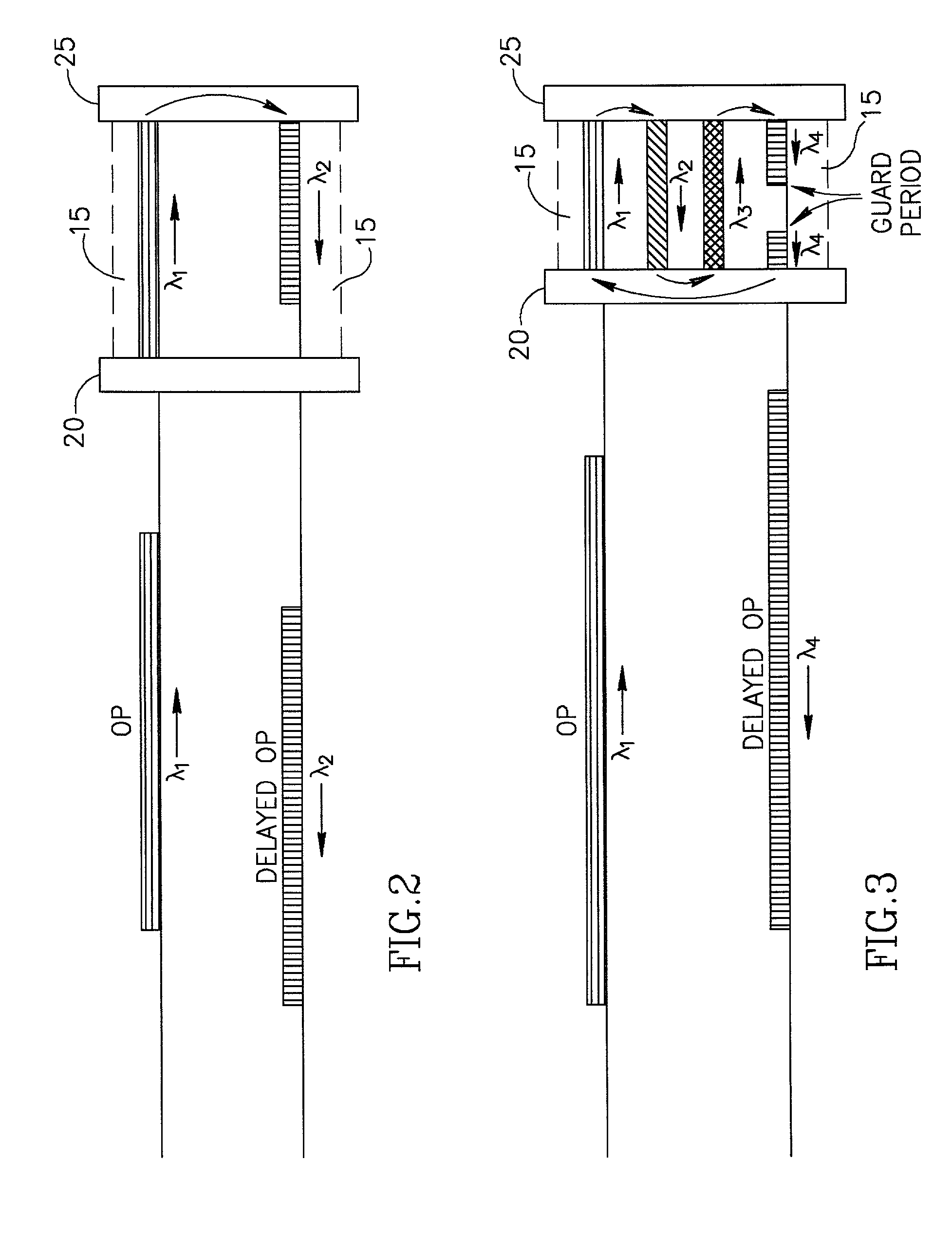
[0101]The apparatus 10 preferably includes optical retransmission units at at least two ends of an optical medium 15. For simplicity of depiction and description, and without limiting the generality of the foregoing, only two optical retransmission units 20 and 25 at two respective ends 30 and 35 of the optical medium 15 are shown by way of example in FIG. 1 and referred to herein below.

[0102]The optical retransmission units 20 and ...


PUM


Abstract

A delayed optical signal is generated from an inputted optical signal by cyclically transmitting the inputted optical signal between at least two ends of an optical medium and outputting the inputted optical signal from one of the ends of the optical medium after at least one transmission cycle via the optical medium. Each transmission of the inputted optical signal in a direction via the optical medium is carried out over a wavelength resource that is different from a wavelength resource used in a preceding transmission of the inputted optical signal in a direction via the optical medium. Interference among repeated transmissions of the inputted optical signal via the optical medium is therefore minimized or even avoided. Related apparatus and method are also described.

Description

FIELD OF THE INVENTION[0001]The present invention generally relates to delaying of optical signals and more particularly to delaying of optical signals for optical buffering and optical storage applications.BACKGROUND OF THE INVENTION[0002]Today, fiber delay lines (FDLs) are used to provide optical buffering in many applications, such as optical switching applications. For example, in optical packet switching delaying of optical packets is typically required, as part of traffic engineering, in order to resolve bandwidth contention.[0003]However, existing FDLs typically provide only limited delays for optical signals. Therefore, techniques and apparatus that can be used to provide extended delays for optical signals are considered as highly desired.[0004]Some aspects of technologies and related art that may be useful in understanding the present invention are described in the following publications:[0005]an article entitled “Architectural and Technological Issues for Future Optical I...

Claims


Application Information

Patent Timeline
IPC IPC(8): H04J14/08G01J1/04G01J1/42G01J5/08H04J14/02H04Q11/00
CPCH04J14/02H04J14/08H04J14/0223H04Q2011/002H04J14/0287H04J14/0284
Inventor HANDELMAN, DORON
Owner F POSZAT HU
Why Eureka
Eureka Blog
Learn More