
Distributed-mass micromachined gyroscopes operated with drive-mode bandwidth enhancement

a micro-machined gyroscope and drive-mode technology, applied in the direction of acceleration measurement using interia forces, devices using electric/magnetic means, instruments, etc., can solve the problem that none of the symmetric designs can provide the required degree of mode-matching without feedback control, and the mechanical coupling between the drive and sense modes is minimized. the effect of instability and dri

Active Publication Date: 2006-09-05
RGT UNIV OF CALIFORNIA
View PDF5 Cites 62 Cited by
  • Summary
  • Abstract
  • Description
  • Claims
  • Application Information

AI Technical Summary

Benefits of technology

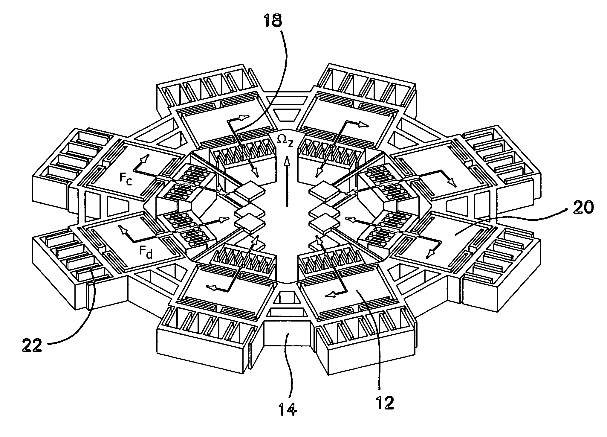
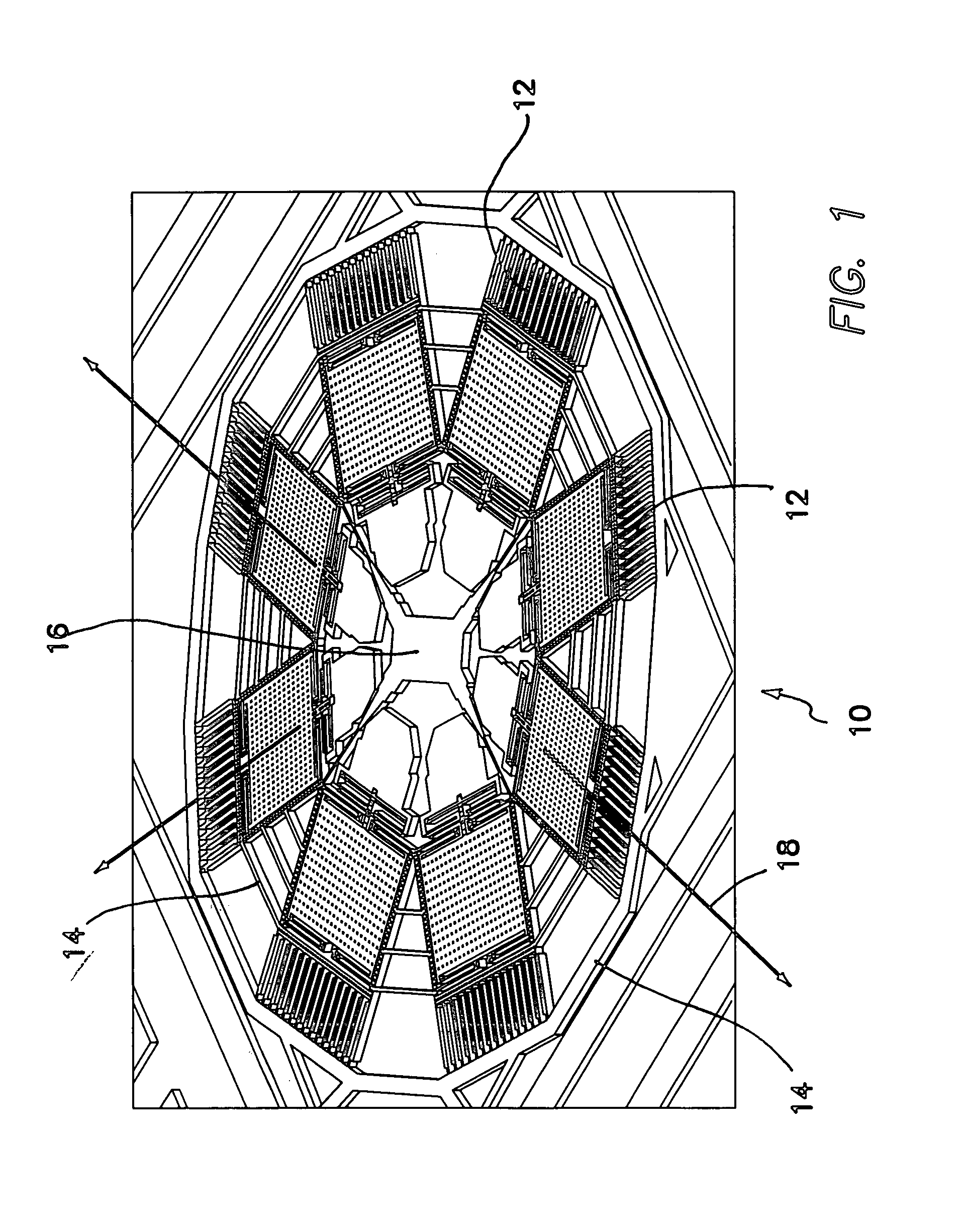
The invention is a distributed-mass micromachined gyroscope that includes multiple drive mode oscillators that are symmetrically distributed around a supporting frame. The drive mode oscillators have different resonance frequencies that are designed to be in the same frequency band, so that mode-matching requirements are relaxed and robustness against parameter fluctuations is achieved. The frame lies in a tangential plane and the drive mode oscillators have drive axes in the tangential plane and are driven in phase with each other. The frame has a multiplicity of tangent sides and each drive mode oscillator is constrained in the tangential direction with respect to the frame. The frame has an anchored center and the drive mode oscillators are distributed symmetrically around the anchored center. The drive actuation applies a corresponding drive force to the drive mode oscillator and the sensing electrodes attached to the frame can sense movement of the drive mode oscillator. The gyroscope is nominally operated in a flat region of the Coriolis torque frequency response. The invention provides a method of operating the distributed-mass micromachined gyroscope.

Problems solved by technology

For the devices packaged in vacuum to enhance the sensitivity, the bandwidth of the resonance peaks is extremely narrow; leading to much tighter mode matching requirements.
However, especially for lightly-damped devices, the mode-matching requirement is well beyond fabrication tolerances; and none of the symmetric designs can provide the required degree of mode-matching without feedback control.
Furthermore, as the modes are matched more closely, the mechanical interference between the modes becomes more significant, resulting in operation instability and drift.
However, the scarce capabilities of photolithography and micro-fabrication processes, and the resulting inherent imperfections in the mechanical structure significantly limits the performance, stability, and robustness of MEMS gyroscopes.
Thus, fabrication and commercialization of high-performance and reliable MEMS gyroscopes that require picometer-scale displacement measurements of a vibratory mass have proven to be extremely challenging.
The limitations of the photolithography-based micromachining technologies defines the upper-bound on the performance and robustness of micromachined gyroscopes.
The mode-matching problem and the quadrature error due to the resulting fabrication imperfections are the two major challenges in MEMS gyroscope design.

Method used


Image

  • Distributed-mass micromachined gyroscopes operated with drive-mode bandwidth enhancement
  • Distributed-mass micromachined gyroscopes operated with drive-mode bandwidth enhancement
  • Distributed-mass micromachined gyroscopes operated with drive-mode bandwidth enhancement

Examples


Embodiment Construction

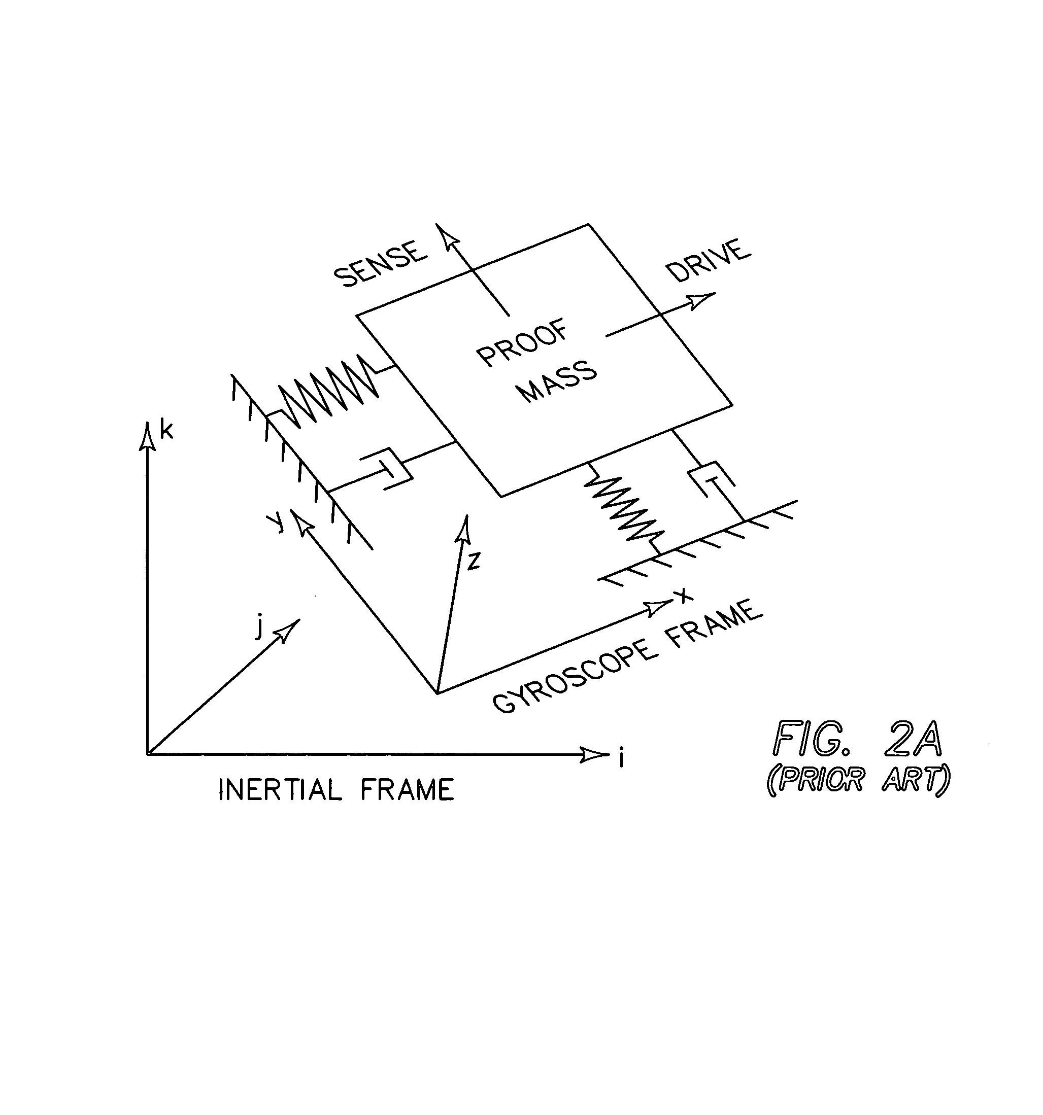
[0051]The invention provides a micromachined z-axis rate gyroscope with multidirectional drive-mode, that increases the drive-mode bandwidth for relaxing mode-matching requirement, and completely decouples the drive and sense modes. By utilizing multiple drive-mode oscillators with incrementally spaced resonance frequencies, wide-bandwidth response is achieved in the drive-mode, leading to reduced sensitivity to structural and thermal parameter fluctuations. Quadrature error and zero-rate-output are also minimized, due to the enhanced decoupling of multi-directional linear drive-mode and the torsional sense-mode. Bulk-micromachined prototypes have been fabricated in a one-mask SOI-based process, and experimentally characterized.

[0052]The distributed-mass gyroscope (DMG) of the invention advances the art by employing multiple linear drive-modes completely decoupled from the rotational sense-mode; while providing a wide-band robust drive-mode. Here we present the design and detailed c...


PUM


Abstract

A micromachined z-axis rate gyroscope with multidirectional drive-mode has an increased drive-mode bandwidth for relaxing mode-matching requirement in which the drive and sense modes are completely decoupled. By utilizing multiple drive-mode oscillators with incrementally spaced resonance frequencies, wide-bandwidth response is achieved in the drive-mode, leading to reduced sensitivity to structural and thermal parameter fluctuations. Quadrature error and zero-rate-output are also minimized, due to the enhanced decoupling of multi-directional linear drive-mode and the torsional sense-mode. Bulk-micromachined prototypes have been fabricated in a one-mask SOI-based process, and is experimentally characterized.

Description

BACKGROUND OF THE INVENTION[0001]1. Field of the Invention[0002]The invention is in the field of micromachined z-axis rate gyroscopes and in particular to gyroscopes with a multidirectional drive-modes.[0003]2. Description of the Prior Art[0004]With their dramatically reduced cost, size, and weight, MEMS gyroscopes potentially have a wide application spectrum in the aerospace industry, military, automotive industry and consumer electronics market. The applications are diverse, including high performance navigation and guidance systems, automotive safety systems like yaw and tilt control, roll-over protection and next generation airbag and antilock brake systems. A wide range of consumer electronics applications include image stabilization in video cameras, virtual reality products, pointing devices, and game industry. Miniaturization of gyroscopes also enable higher-end applications like micro-satellites, microrobotics, and even implantable devices to cure vestibular disorders.[0005...

Claims


Application Information

Patent Timeline
Patent Type & Authority Patents(United States)
IPC IPC(8): G01P9/04G01C19/00
CPCG01C19/5719
Inventor ACAR, CENKSHKEL, ANDREI M.
Owner RGT UNIV OF CALIFORNIA
Learn More