Piston arrangement

a technology of pistons and cylinders, applied in the direction of trunk pistons, machines/engines, plungers, etc., can solve the problems that the piston made of metal sheets cannot adopt high pressure, and achieve the effect of reducing the diameter, reducing the risk, and reducing the negative effect of the piston operating behaviour

Active Publication Date: 2006-09-05
SECOP GMBH +1
View PDF30 Cites 15 Cited by
  • Summary
  • Abstract
  • Description
  • Claims
  • Application Information

AI Technical Summary

Benefits of technology

[0010]With this embodiment, a reduction of the costs can be achieved primarily in that the piston itself can be made in a cheap manner. Merely a relatively thin metal sheet is required, with a thickness in the area between 0.6 and 1 mm, particularly in the area 0.7 to 0.8 mm. Such a metal sheet can easily be reshaped to some kind of cup, for example by means of deep-drawing. The bottom of the cup then forms the piston head and the circumferential wall forms the piston skirt. Thus, it is avoided to make the piston as a cast unit. Usually, a piston made of metal sheet is not able to adopt the high pressures, which occur in a refrigerant compressor. For this reason, the reinforcement element is used, which is located inside the piston. The reinforcement element has two tasks. Firstly, it reinforces the piston head, and secondly, with its bearing area it forms a support for adopting the ball of the ball joint arrangement. The ball, the reinforcement element and the piston are then simply kept together by the safety element, which simplifies the manufacturing substantially. Such a piston further has the advantage that it has a small mass. This has a favourable effect on the vibration behaviour of a compressor provided with such a piston, for example a refrigerant compressor. As the forces required for accelerating the piston are smaller, less energy and smaller balancing weights are required.
[0025]Preferably, the piston skirt has, between the piston head and the fixing area, a further radially inwardly shaped axial section, on which the safety element bears from the inside. This axial section firstly has a certain supporting function, that is, seen in the axial direction the safety element is held in the piston at two positions. Secondly, the axial section also has the function of delimiting a channel between the safety element and the piston skirt, which channel is used for an oil flow. Finally, the piston skirt gets more rigid, which is favourable for a grinding process for working the circumference of the piston.

Problems solved by technology

Usually, a piston made of metal sheet is not able to adopt the high pressures, which occur in a refrigerant compressor.

Method used


Image

  • Piston arrangement
  • Piston arrangement

Examples


Embodiment Construction

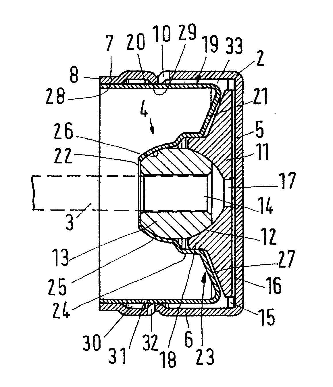
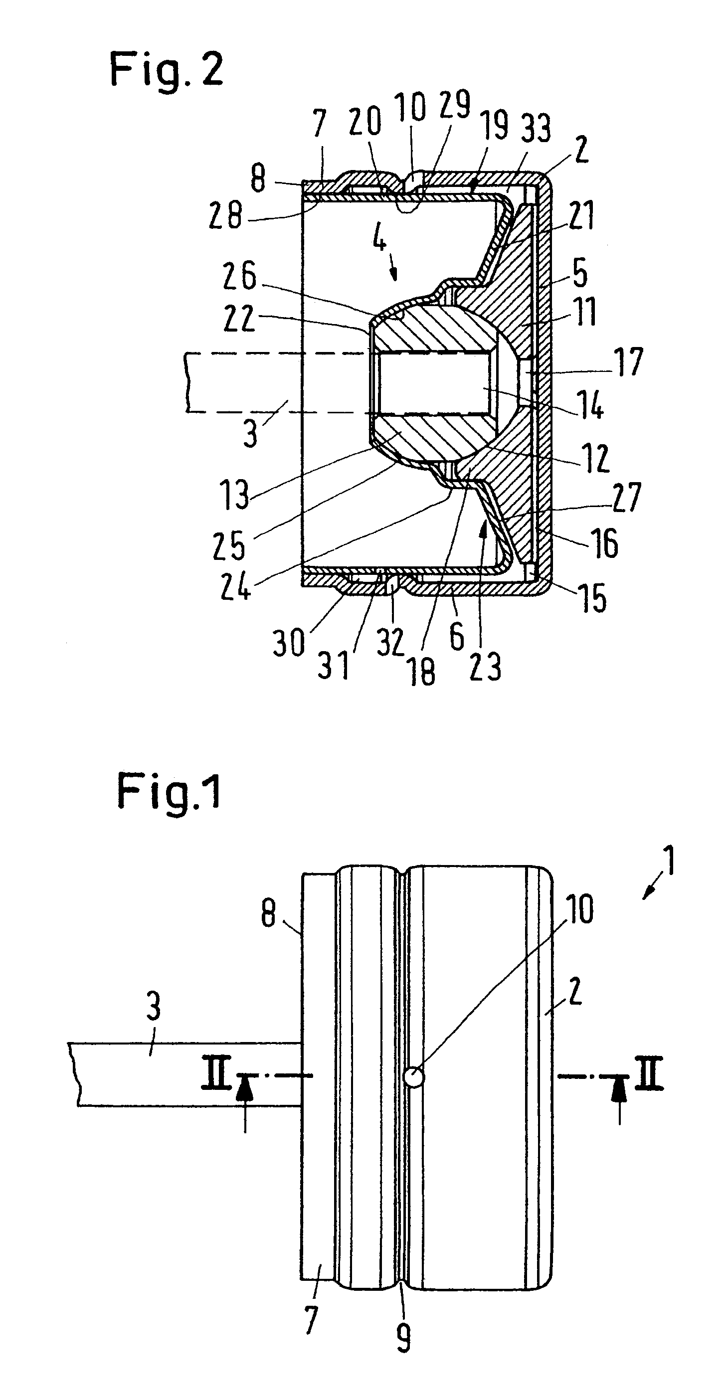
[0030]A piston arrangement 1 has a piston 2 and a connecting rod 3, which are connected with each other by means of a ball joint arrangement 4, which is only shown in FIG. 2. In FIG. 2, the connecting rod 3, with which the piston 2 shall be driven, is merely shown with dotted lines.

[0031]The piston 2 has a piston head 5 and a piston skirt 6, the piston head 5 forming a front side of the piston 2 and the piston skirt 6 forming a circumferential wall of the piston 2. As can be seen from FIG. 1, the piston skirt has a first diameter reduction 7, which is located at an end 8 facing away from the piston head 5, and a second diameter reduction 9, which is located in the middle of the piston skirt and forms a circumferential groove. In this second diameter reduction 9 is provided an oil outlet bore 10, which will be explained in detail in the following.

[0032]The piston 2 is deep-drawn from a relatively thin metal sheet with a thickness in the area from 0.7 to 0.8 mm. Thus, it is relatively...


PUM


Abstract

The invention concerns a piston arrangement having a piston with a piston head and a piston skirt and a connecting rod, which is connected with the piston via a ball joint arrangement comprising a ball, the ball being held in the piston by means of a safety element.

Description

CROSS-REFERENCE TO RELATED APPLICATIONS[0001]This application is entitled to the benefit of and incorporates by reference essential subject matter disclosed in German Patent Application No. 103 56 404.7 filed on Dec. 3, 2003.FIELD OF THE INVENTION[0002]The invention concerns a piston arrangement having a piston with a piston head and a piston skirt and a connecting rod, which is connected with the piston via a ball joint arrangement comprising a ball, the ball being held in the piston by means of a safety element.BACKGROUND OF THE INVENTION[0003]Such a piston arrangement is known from U.S. Pat. No. 2,451,216. Here, the piston head has an axially inwards extending projection with a spherical recess, in which the ball is supported. In an alternative embodiment, the spherical design is formed by a sheet metal element, which is inserted in the piston. Such a piston must be usable for a domestic refrigerator.[0004]The connection between a piston and a connecting rod by means of a ball jo...

Claims


Application Information

Patent Timeline
Patent Type & Authority Patents(United States)
IPC IPC(8): F16J1/22
CPCF16J1/22
Inventor PETERSEN, CHRISTIANLASSEN, HEINZ OTTONOMMENSEN, MARTENIVERSEN, FRANK HOLM
Owner SECOP GMBH
Why Eureka
Try Eureka