Gas filtering and recirculating device for general machine

a recirculating device and general machine technology, applied in machines/engines, liquid fuel feeders, combustion air/fuel air treatment, etc., can solve problems such as the compromised function of the gas filtering and recirculating devi

Inactive Publication Date: 2006-09-05
KYMCO
View PDF19 Cites 11 Cited by
  • Summary
  • Abstract
  • Description
  • Claims
  • Application Information

AI Technical Summary

Benefits of technology

[0009]i) Gas generated by fuel in the fuel tank can be completely filtered and absorbed by the gas filtering and recirculating device since the gas filtering and recirculating device is provided above the fuel tank. Also, oil spilled out of the full fuel tank may not fall on the gas filtering and recirculating device because the gas filtering and recirculating device is disposed above the fuel tank. Otherwise, the function of the gas filtering and recirculating device is compromised. Moreover, oil drops formed by accumulating gas in the gas filtering and recirculating device may smoothly exit the oil drain since the oil drain is disposed below the air outlet. This can avoid the blocking of the gas filtering and recirculating device. Otherwise, the engine may not start or the operating engine may stop operating suddenly.
[0011]iii) Oil drops formed by accumulating gas in the gas filtering and recirculating device may smoothly exit the oil drain to fall on an oil pan (i.e., cold area) on the-top of the fuel tank only without flowing to other areas. As such, danger caused by a separate hot area (e.g., the exhaust manifold and the heat resisting cover member) can be prevented.
[0012]iv) The gas filtering and recirculating device is inclined at an angle of α with respect to a horizontal plane passing a top of the fuel tank. As such, oil drops may smoothly exit the oil drain to fall on the oil pan.

Problems solved by technology

The drawback is that for facilitating fuel in the fuel tank flowing into the carburetor an air outlet is provided on the top of the fuel tank, the air outlet undesirably directly discharging toxic gas generated by fuel in the fuel tank into the atmosphere via the air outlet.
Otherwise, the function of the gas filtering and recirculating device is compromised.

Method used


Image

  • Gas filtering and recirculating device for general machine
  • Gas filtering and recirculating device for general machine
  • Gas filtering and recirculating device for general machine

Examples


Embodiment Construction

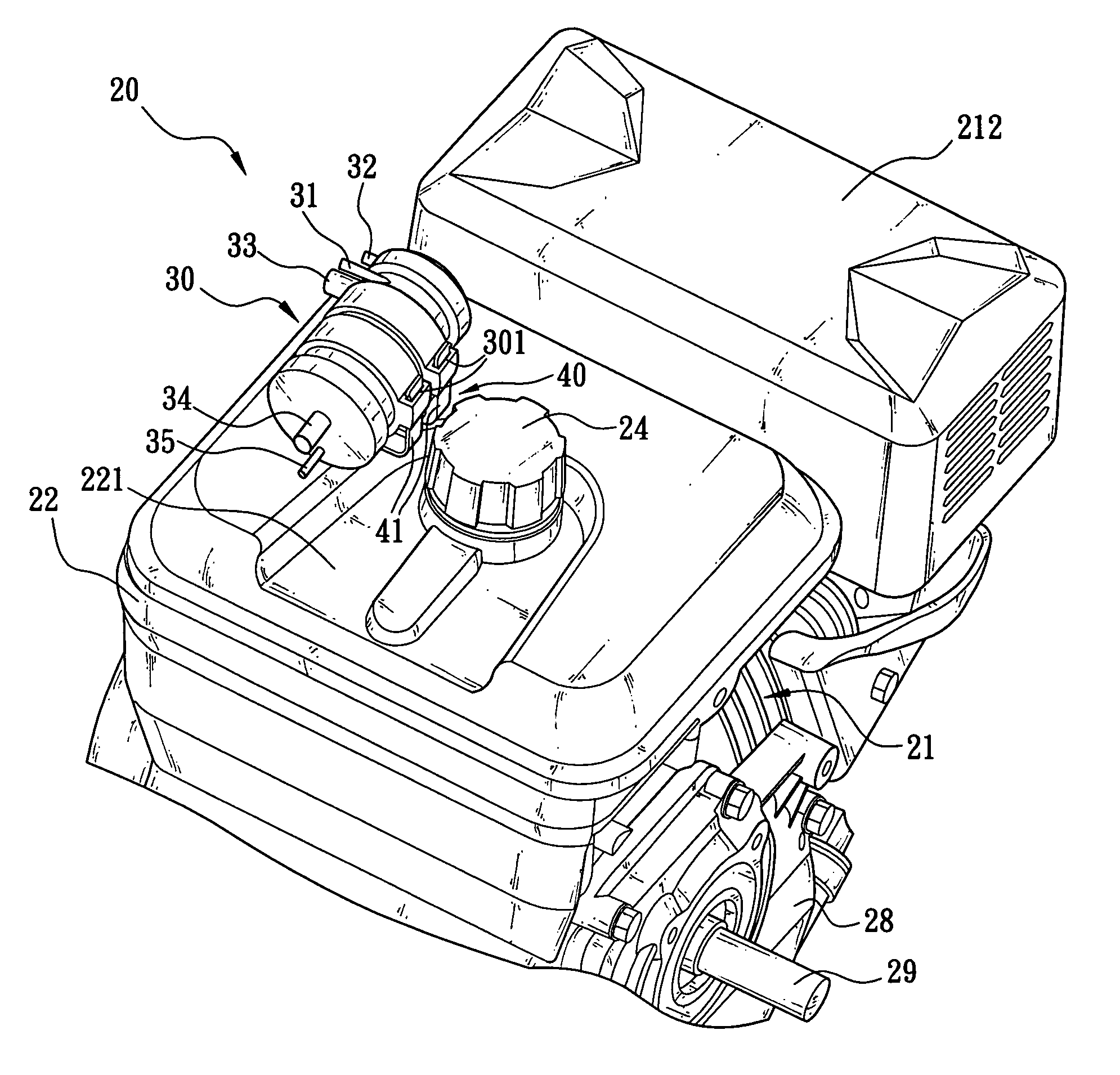
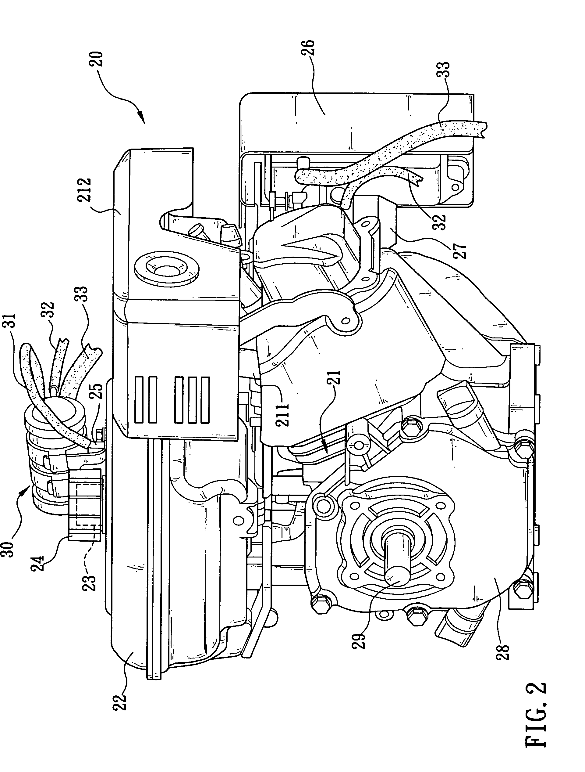
[0019]Referring to FIG. 2, there is shown a general machine 20 according to a preferred embodiment of the invention. The general machine 20 comprises an engine 21, a fuel tank 22 provided above the engine 21, a fuel inlet 23 provided on a top of the fuel tank 22 in which fuel is flowed into the fuel tank 22 via the fuel inlet 23, a cover 24 enclosed the fuel inlet 23 for preventing fuel from spilling out of the fuel inlet 23, and a gas outlet 25 provided on the top of the fuel tank 22 proximate the fuel inlet 23.

[0020]Moreover, the general machine 20 further comprises an air filter 26 provided besides the engine 21, a carburetor 27 for mixing fuel supplied from the fuel tank 22 with pure air supplied from the air filter 26 to make an explosive mixture which is then supplied to the engine 21 for combustion, and a crank case 28 having a crank shaft 29 adapted to rotate in response to the combustion. As an end, the purpose of developing mechanical power for starting motion in another m...


PUM


Abstract

The present invention relates to a gas filtering and recirculating device for a general machine having an engine and a fuel tank provided above the engine, which is mountable above the fuel tank and comprises at its one end an air outlet in fluid communication with atmosphere and an oil drain below the air outlet and above the fuel tank such that the oil drain is proximate the fuel tank, enabling the gas filtering and recirculating device to completely filter and absorb gas generated by fuel in the fuel tank and prevent the gas from discharging into the atmosphere via an air outlet in the fuel tank and causing air pollution.

Description

FIELD OF THE INVENTION[0001]The present invention relates to a pollution control devices' more particularly to a gas filtering and recirculating device capable of completely filtering and absorbing gas generated by fuel in a fuel tank of a general machine and preventing the gas generated by the fuel from discharging into the atmosphere via an air outlet in the fuel tank and causing air pollution.BACKGROUND OF THE INVENTION[0002]Pollution (e.g., water pollution, noise, air pollution, etc.) has become a global issue as technology makes progress rapidly. Also, more people pay attention to pollution because people are aware of the importance of environmental protection. Further, many governments have given strict laws and enforced the same so as to effectively control pollution. For example, for decreasing air pollution toxic gas generated by fuel in a fuel tank is not allowed to discharge into the atmosphere as enacted by the governments.[0003]However, air pollution caused by machines ...

Claims


Application Information

Patent Timeline
Patent Type & Authority Patents(United States)
IPC IPC(8): F02M33/02
CPCF02M37/20F02M25/0854B60K2015/03557
Inventor LIN, TSANG-MAOHSIEH, CHUN-HUNG
Owner KYMCO
Why Eureka
Try Eureka