Method of maintaining constant arterial PCO2 and measurement of anatomic and alveolar dead space

Inactive Publication Date: 2006-09-05
THORNHILL SCI INC
View PDF17 Cites 24 Cited by
  • Summary
  • Abstract
  • Description
  • Claims
  • Application Information

AI Technical Summary

Benefits of technology

[0068]When minute ventilation is greater than or equal to the rate of atmospheric air aspirated, the above-mentioned preferred circuit ensures that the patient receives all the atmospheric air aspirated into the circuit, independent of the pattern of breathing; since atmospheric air alone enters the fresh gas reservoir and exhaled gas enters its own separate reservoir and all the aspirated air is delivered to the patient during inhalation before rebreathed exhaled gas. The atmospheric air aspirator preferably large enough not to fill to capacity during prolonged exhalation, when the total minute ventilation exceeds the rate of atmospheric air aspiration ensuring that under these circumstances atmospheric air continues to enter the circuit uninterrupted during exhalation. The preferred circuit prevents rebreathing at a minute ventilation equal to the rate of air being aspirated into the atmospheric air aspirator because the check valve in the interconnecting conduit does not open to allow rebreathing of previously exhaled gas unless a sub-atmospheric pressure less than that generated by the recoil of the aspirator exists on the inspiratory side of the conduit of the circuit. The circuit provides that after the check valve opens, alveolar gas is rebreathed in preference to dead space gas because the interconnecting conduit is located such that exhaled alveolar gas contained in the tube c

Problems solved by technology

In addition, if minute ventilation is temporarily less than fresh gas flow, fresh gas is lost from the circuit due to the proximity of the fresh gas inlet to the relief valve.
Fresh gas is lost because during expiration, fresh gas mixes with expir

Method used


Image

  • Method of maintaining constant arterial PCO2 and measurement of anatomic and alveolar dead space
  • Method of maintaining constant arterial PCO2 and measurement of anatomic and alveolar dead space
  • Method of maintaining constant arterial PCO2 and measurement of anatomic and alveolar dead space

Examples


Embodiment Construction

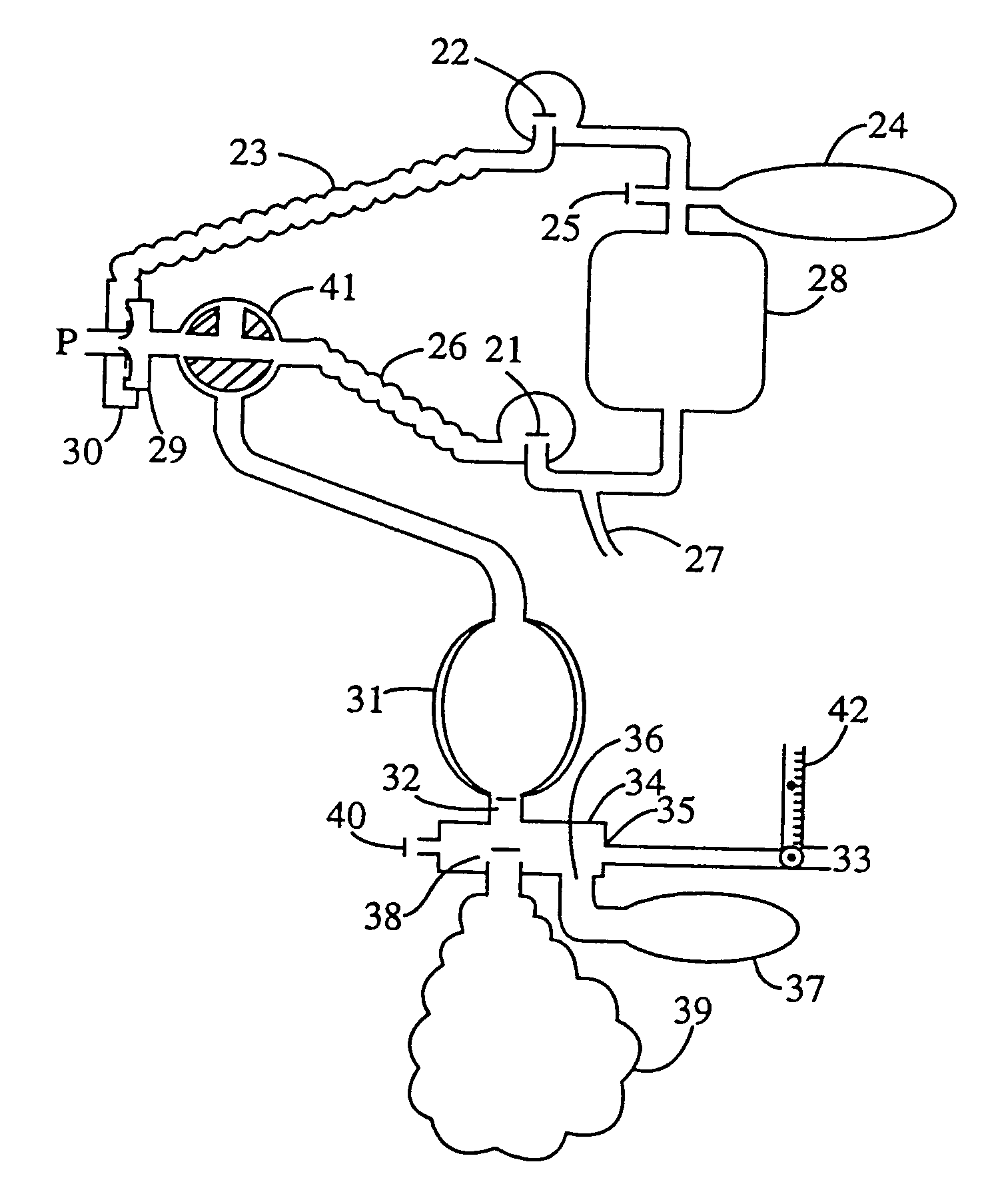
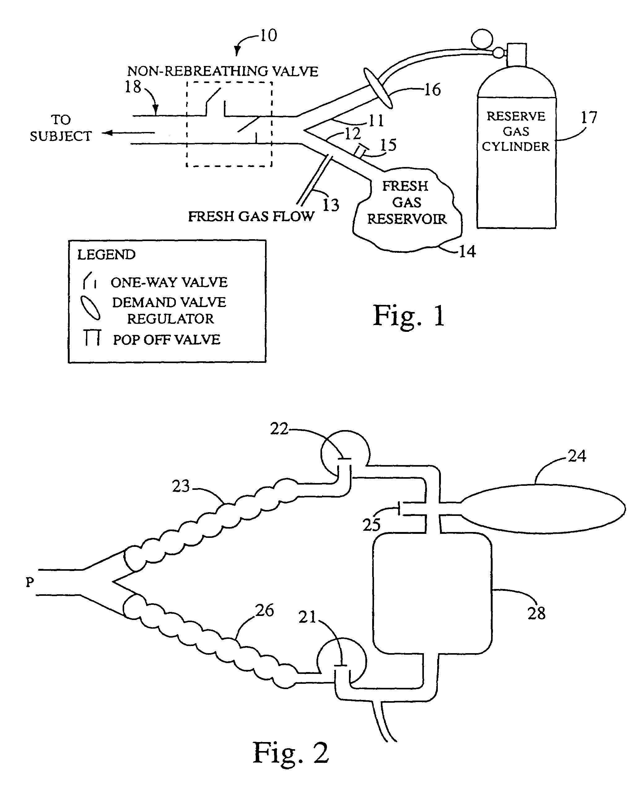
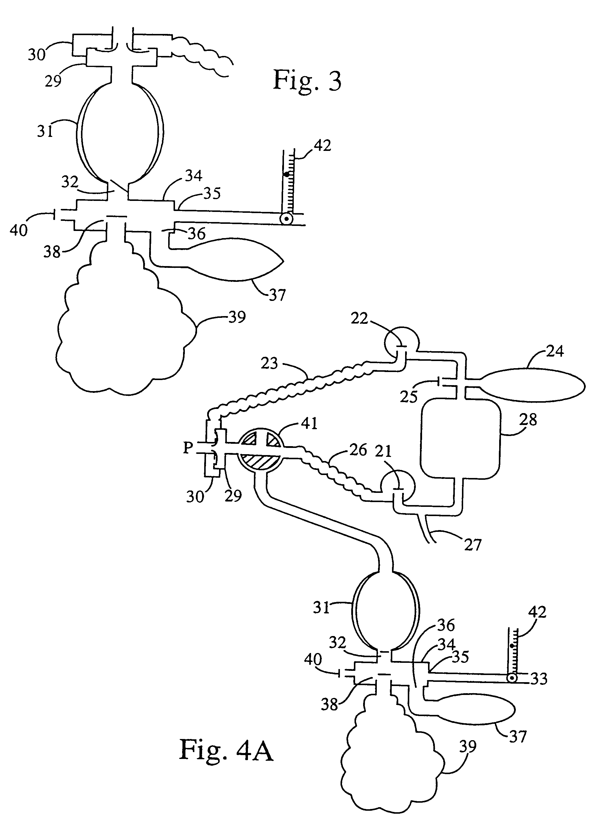
[0082]PCT Application No. WO98 / 41266 filed by Joe Fisher (WO98 / 41266) teaches a method of accelerating the resuscitation of a patient which has been anaesthetized by providing the patient with a flow of fresh gas (FGF) and a source of reserve gas is expressly incorporated herein by reference. As thought in WO98 / 41266, when the patient breathes at a rate less than or equal to the fresh gas flowing into the circuit, all of the inhaled gas is made up of fresh gas. When the patient's minute ventilation exceeds the fresh gas flow, the inhaled gas is made up of all of the fresh gas and the additional gas is provided by “reserve gas” with a composition similar to the fresh gas but with CO2 added such that the concentration of CO2 in the reserve gas of about 6% is such that its partial pressure is equal to the partial pressure of CO2 in the mixed venous blood. At no time while using this method will the patient rebreathe gas containing anaesthetic. In order to accelerate the resuscitation o...


PUM


Abstract

A method to maintain isocapnia for a subject. A fresh gas is provided to the subject when the subject breathes at a rate less than or equal to the fresh gas flowing to the subject. The fresh gas flow equal to a baseline minute ventilation minus a dead space gas ventilation of the subject contains a physiological insignificant amount of CO2. An additional reserve gas is provided to the subject when the subject breathes at a rate more than the fresh gas flowing to the subject. The reserve gas has a partial pressure of carbon dioxide equal to an arterial partial pressure of carbon dioxide of the subject. A breathing circuit is applied to the method to maintain isocapnia for a subject. The breathing circuit has an exit port, a non-rebreathing valve, a source of fresh gas, a fresh gas reservoir and a reserve gas supply.

Description

RELATED APPLICATIONS[0001]The present application is a continuation of U.S. application Ser. No. 10 / 135,655 entitled “METHOD OF MAINTAINING CONSTANT ATERIAL PCO2 AND MEASUREMENT OF ANATOMIC AND ALVEOLAR DEAD SPACE” filed Apr. 30, 2002, now U.S. Pat. No. 6,799,570 which is a continuation-in-part of application Ser. No. 09 / 676,899, filed on Oct. 2, 2000.STATEMENT RE FEDERALLY SPONSORED RESEARCH / DEVELOPMENT[0002](Not applicable)BACKGROUND OF INVENTION[0003]The present invention relates to a method to maintain isocapnia when breathing exceeds baseline breathing and a circuit therefor. Preferably, the circuit includes a non-rebreathing valve, a source of fresh gas, a fresh gas reservoir and a source of gas to be inhaled when minute ventilation exceeds fresh gas flow. Preferably the flow of the fresh gas is equal to minute ventilation minus anatomic dead space. Any additional inhaled gas exceeding fresh gas flow has a partial pressure of CO2 equal to the partial pressure of CO2 of arteria...

Claims


Application Information

Patent Timeline
IPC IPC(8): A61M16/00A61B5/083A61B5/087A61M16/12A61M16/20
CPCA61B5/0836A61B5/087A61B5/4821A61M16/12Y10S128/914A61M2202/0225A61M16/208A61M2202/0007
Inventor FISHER, JOSEPHVESELY, ALEXSASANO, HIROSHIISCOE, STEVESOMOGYI, RONALD
Owner THORNHILL SCI INC
Why Eureka
Try Eureka