Current reference circuit with voltage-to-current converter having auto-tuning function

a voltage-to-current converter and reference circuit technology, applied in the direction of electric variable regulation, process and machine control, instruments, etc., can solve the problem of degrading the accuracy of the voltage-to-current converting circuit shown in fig. 1

Active Publication Date: 2006-09-05
SAMSUNG ELECTRONICS CO LTD
View PDF14 Cites 24 Cited by
  • Summary
  • Abstract
  • Description
  • Claims
  • Application Information

AI Technical Summary

Benefits of technology

[0026]As a result, the auto-tuner receives the input clock signal and generates the tuning voltage, thereby uniformly maintaining the transconductance value of the transconductance circuit.

Problems solved by technology

However, since a resistance value of the resistor R is easily affected by variations in manufacturing process and operational temperature, accuracy of the voltage-to-current converting circuit shown in FIG. 1 may be degraded.

Method used


Image

  • Current reference circuit with voltage-to-current converter having auto-tuning function
  • Current reference circuit with voltage-to-current converter having auto-tuning function
  • Current reference circuit with voltage-to-current converter having auto-tuning function

Examples


Embodiment Construction

[0050]Hereinafter, the present invention will be described in detail with reference to the accompanying drawings.

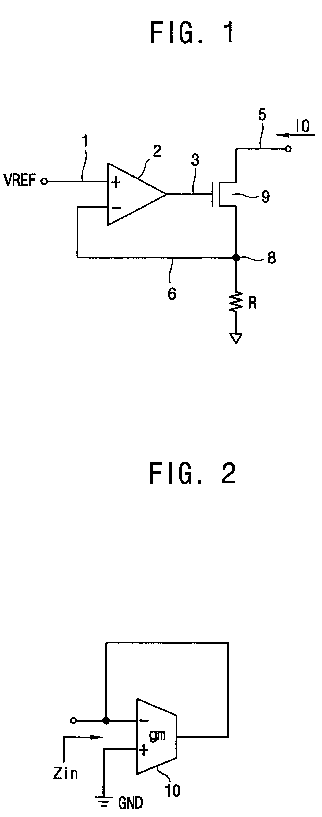
[0051]FIG. 2 is a circuit diagram showing an equivalent resistance of a transconductance circuit.

[0052]Referring to FIG. 2, a transconductance circuit 10 has an output terminal tied back to an inverting input terminal and a noninverting input terminal connected to a ground GND. In the transconductance circuit 10 shown in FIG. 2, an input impedance (Zin) is 1 / gm that is an equivalent resistance of the transconductance circuit 10.

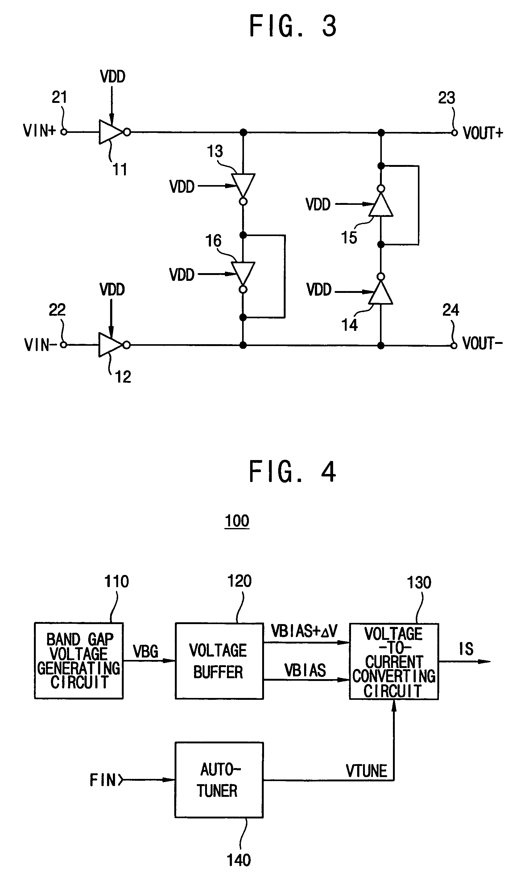
[0053]FIG. 3 is a circuit diagram showing a conventional transconductance circuit. The transconductance (gm) circuit of FIG. 3 has been disclosed in U.S. Pat. No. 6,191,655. The transconductance circuit of FIG. 3 is called ‘Nauta's gm circuit’. In FIG. 3, the transconductance circuit includes first, second, third, fourth, fifth and sixth inverters 11, 12, 13, 14, 15 and 16. The first and second inverters 11 and 12 generate a transconductance gain g...


PUM


Abstract

A current reference circuit has a band gap voltage generating circuit, a voltage buffer, a voltage-to-current converting circuit and an auto-tuner. The band gap voltage generating circuit generates a band gap reference voltage. The voltage buffer generates a first bias voltage and a second bias voltage. The voltage-to-current converting circuit generates a source current in response to a tuning voltage. The auto-tuner generates the tuning voltage to maintain a transconductance. Thus, the current reference circuit may automatically adjust the transconductance, so that the current reference circuit may supply the source current that is stable against temperature and process variations.

Description

CROSS REFERENCE TO RELATED APPLICATION[0001]This application relies for priority upon Korean Patent Application No. 2004-889 filed on Jan. 7, 2004, the contents of which are herein incorporated by reference in its entirety.BACKGROUND OF THE INVENTION[0002]1. Field of the Invention[0003]The present invention relates to a current reference circuit. More particularly, the present invention relates to a current reference circuit having a voltage-to-current converting circuit with an auto-tuning function.[0004]2. Description of the Related Art[0005]A current reference circuit supplies a bias current to an operational amplifier, a filter, an analog-to-digital converter, a digital-to-analog converter, etc. In general, a current reference circuit includes a reference voltage generating circuit that generates a reference voltage and a voltage-to-current converter that converts the reference voltage into a current. In designing a semiconductor integrated circuit using a complementary metal ox...

Claims


Application Information

Patent Timeline
Patent Type & Authority Patents(United States)
IPC IPC(8): G05F3/20G05F3/16G05F1/10G05F3/26
CPCG05F3/262G05F1/10
Inventor KIM, JAE-WAN
Owner SAMSUNG ELECTRONICS CO LTD
Why Eureka
Try Eureka