Variable gain amplifying circuit

a variable gain amplifying circuit and amplifier technology, applied in differential amplifiers, amplifiers with semiconductor devices/discharge tubes, amplifiers, etc., can solve the problems of signal diagnostic, increased bit error rate of communication systems, and inability to meet the requirement of high-precision gain

Active Publication Date: 2006-09-05
REALTEK SEMICON CORP
View PDF10 Cites 22 Cited by
  • Summary
  • Abstract
  • Description
  • Claims
  • Application Information

AI Technical Summary

Benefits of technology

[0008]Another object of the present invention is to provide a variable gain amplifying circuit that can compensate a gain mismatch resulted from the factors of temperature, manufacturing process, supply voltage drift, etc.

Problems solved by technology

However, as long as the amplitude of the I / Q signals has a slight mismatch, the constellation diagram of the signals would be damaged, and the bit error rate (BER) of the communication system would also be increased.
The gain drift of a conventional open-loop amplifier is rather large, so it cannot meet the requirement of highly precise gain.
However, if a highly precise gain is required, e.g. 1.001, then the gain accuracy may be easily affected by a slight error of the resistor values of R1 and R2 since the difference between the values of R1 and R2 is rather small (e.g. R1=1 k ohm, R2=(1 k+1) ohm).
In particular, when the amplifying circuit of FIG. 1 is implemented on an integrated circuit (IC), it is more difficult to achieve a highly precise gain since the factors of temperature, manufacturing process, supply voltage drift, etc. cannot be completely controlled.

Method used


Image

  • Variable gain amplifying circuit
  • Variable gain amplifying circuit
  • Variable gain amplifying circuit

Examples


Embodiment Construction

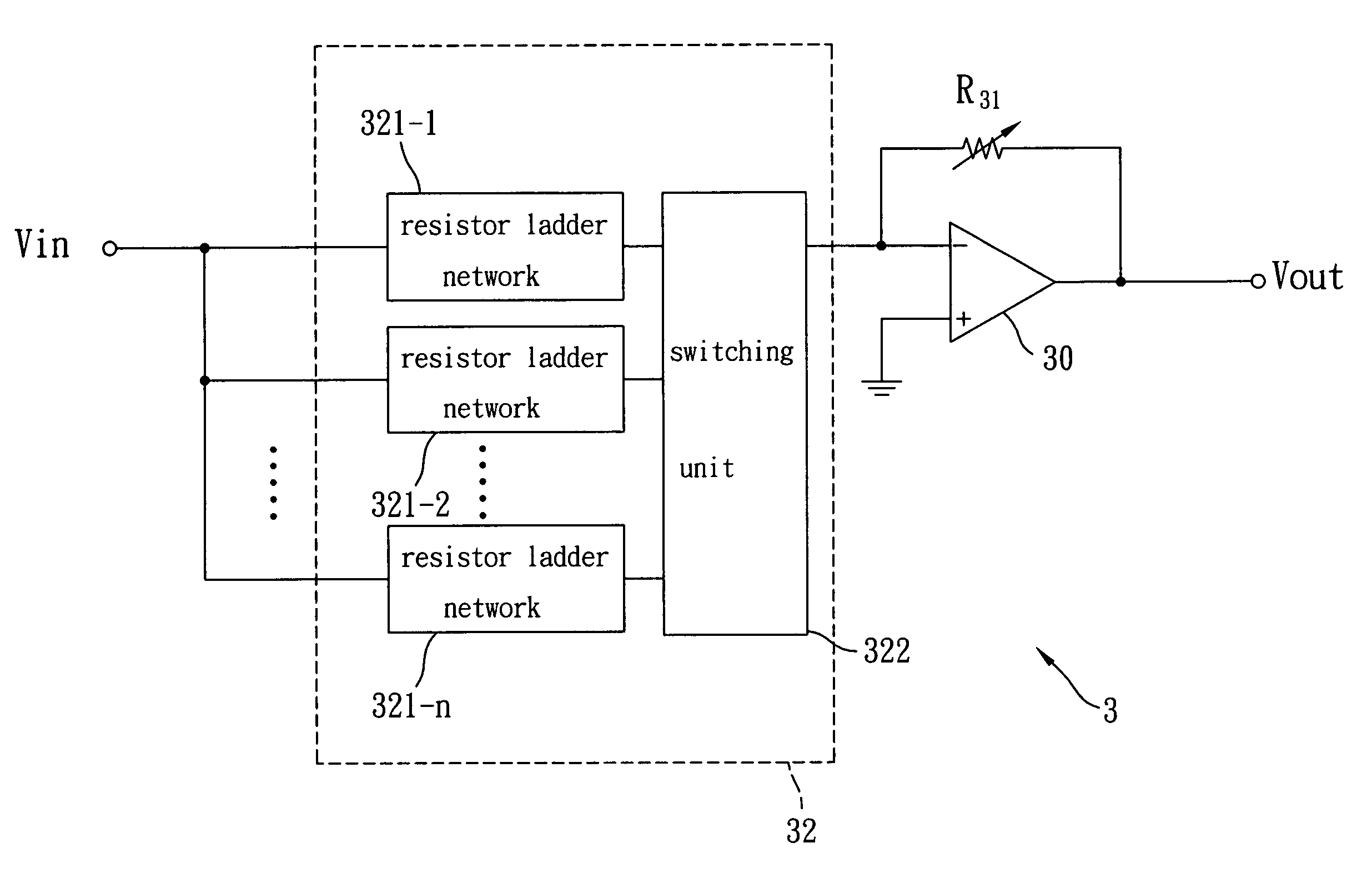
[0016]The present invention employs resistor ladders to adjust the resistor value of a closed-loop amplifying circuit, thereby achieving the goal of precise gain control. The circuit structure and principle of the resistor ladder is described below first.

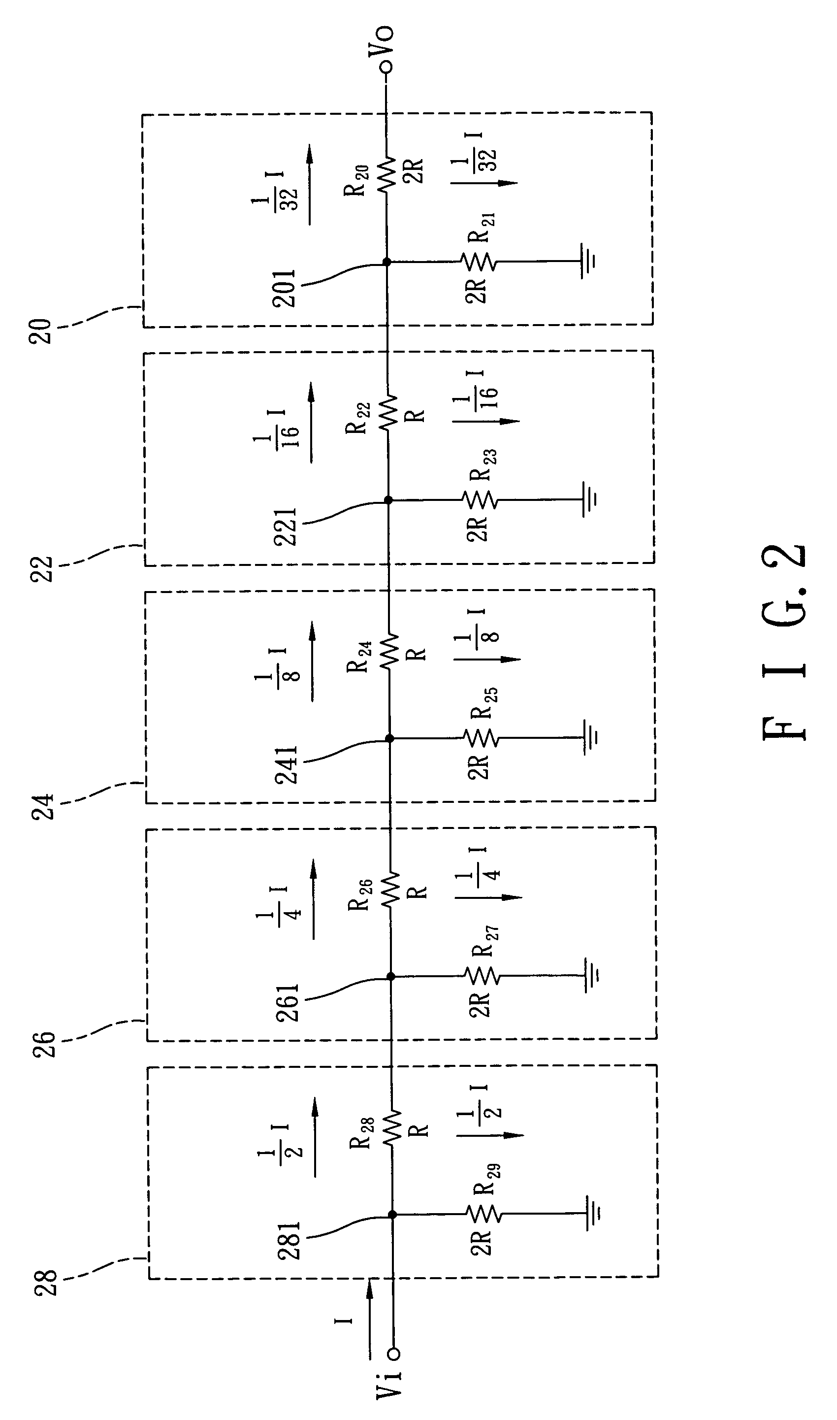
[0017]FIG. 2 is a circuit structure diagram of a 5-step resistor ladder, wherein each of the five steps (i.e. blocks 20, 22, 24, 26 and 28) contains a node (denoted as 201, 221, 241, 261 and 281 respectively) and two current paths. One of the current paths is coupled to ground, and the other is coupled to the node of the next step. In FIG. 2, the relation between the resistor values is not limited originally. However, for the sake of brevity, values of the resistors R20, R21, R23, R25, R27 and R29 are selected as twice of those of the resistors R22, R24, R26 and R28. That is, the resistor ladder in FIG. 2 is a 5-bit R-2R resistor network, whose equivalent circuit is derived as follows: the resistors R20 and R21, are parallel connect...


PUM


Abstract

A variable gain amplifying circuit, which applies a resistor ladder to obtain a more precise gain, is disclosed. The amplifying circuit includes an input, an operational amplifier (op-amp), a resistor unit and a feedback resistor. The feedback resistor is coupled between an output and an inverting input of the op-amp. The resistor unit includes at least one resistor ladder. The resistor unit further includes a switching unit for controlling whether the at least one resistor ladder is coupled between the input of the amplifying circuit and the inverting input of the op-amp. A differential amplifying circuit for more precise gain adjustment is also disclosed.

Description

REFERENCE TO RELATED APPLICATIONS[0001]This application is a continuation-in-part of application with Ser. No. 10 / 748,667, filed Dec. 31, 2003, now U.S. Pub. No. 2004 / 0232981.BACKGROUND OF THE INVENTION[0002](a). Field of the Invention[0003]The present invention relates in general to an electronic circuit, and more particularly to an amplifying circuit with a variable gain.[0004](b). Description of the Prior Arts[0005]In modem circuit design, it is often necessary to provide the signal amplifying function with high accuracy. For example, in a common modulation mechanism for wireless communication, I / Q signals are used in phase modulation or frequency modulation. However, as long as the amplitude of the I / Q signals has a slight mismatch, the constellation diagram of the signals would be damaged, and the bit error rate (BER) of the communication system would also be increased. Thus, an amplifier with a highly precise gain is needed to accurately control the amplitude of the I / Q signal...

Claims


Application Information

Patent Timeline
Patent Type & Authority Patents(United States)
IPC IPC(8): H03G3/10H03G1/00H03G3/30
CPCH03G1/0088
Inventor LEE, CHAO CHENGLIN, YING YAO
Owner REALTEK SEMICON CORP
Why Eureka
Try Eureka