
Method for extra-high speed transformation of time signal into two-dimensional space signal

a technology of time signal and space signal, applied in the field of ultra-fast conversion of two-dimensional information, can solve the problems of space signal converted by such methods, limitation of transformation speed, space signal cannot be observed with any ultra-fast light-receiving device available today, etc., and achieve the effect of ultra-fast conversion of time signal

Inactive Publication Date: 2006-09-05
JAPAN SCI & TECH CORP
View PDF5 Cites 1 Cited by
  • Summary
  • Abstract
  • Description
  • Claims
  • Application Information

AI Technical Summary

Benefits of technology

[0004]Accordingly, an object of the present invention is to provide a method for ultra-fast conversion of time signal into two-dimensional space signal which is capable of realizing ultra-fast conversion of signal form from time signal to two-dimensional space signal without performing active-scan and also is capable of displaying the two-dimensional space signal in a visible region with a temporally steady state.

Problems solved by technology

However, this space-to-time-to-space signal processing method has a problem that must be solved in time-to-two-dimensional space signal conversion technology.
However, although the conventional methods are capable of carrying out ultra-fast conversion into one-dimensional space signal, some of them basically need to perform active scanning for conversion into two or more dimensional space signal and thus have a limitation in transformation speed.
On the other hand, there are some methods that do not need to perform active scanning, but space signal converted by such methods cannot be observed with any ultra-fast light-receiving device available today.

Method used


Image

  • Method for extra-high speed transformation of time signal into two-dimensional space signal
  • Method for extra-high speed transformation of time signal into two-dimensional space signal

Examples


Embodiment Construction

[0028]The present invention has the forgoing features, and the embodiment thereof will be described hereinafter.

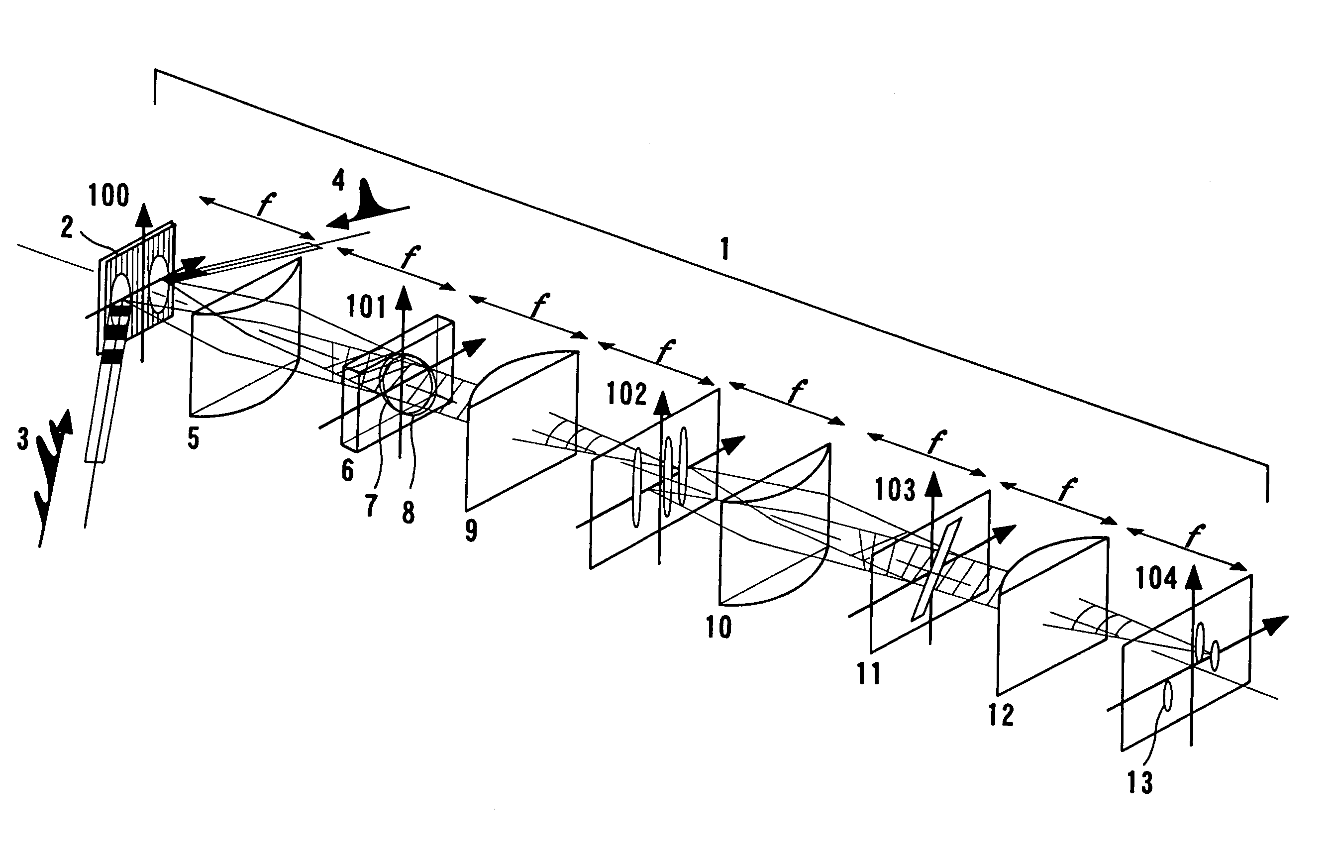
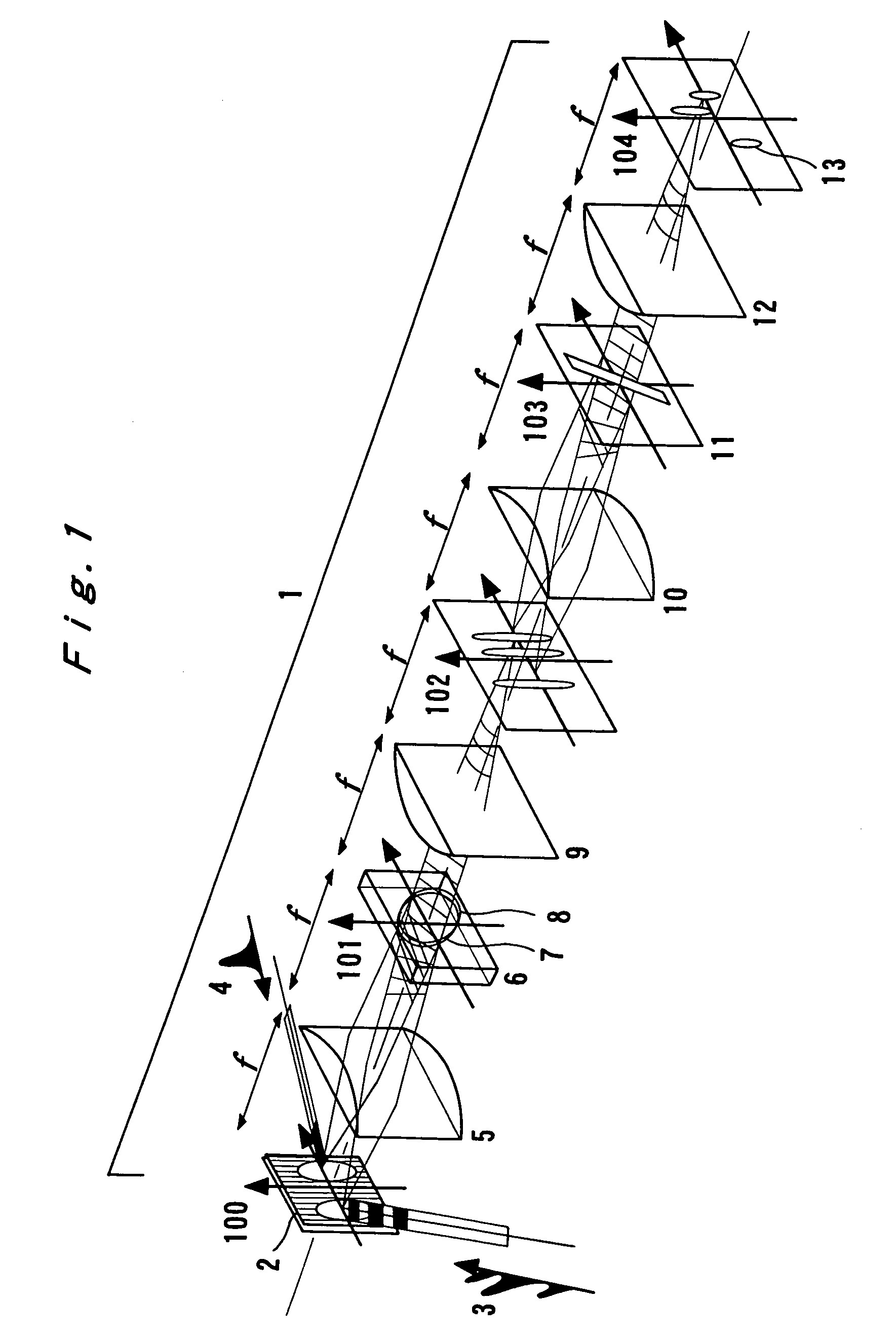
[0029]FIG. 1 shows an example of the structure of the time-to-two-dimensional space signal conversion optical system for performing the method of ultra-fast conversion from time signal to two-dimensional space signal according to the present invention. This time-to-two-dimensional space signal conversion optical system 1 is capable of converting a signal light pulse being a time signal, which is ultra-short pulse laser light in this example, into a two-dimensional space signal corresponding to time and frequency by using a dispersion device such as a diffraction grating, a one-dimensional Fourier transformation lens, a one-dimensional inverse-Fourier transformation lens, a nonlinear crystal for generation of a second-harmonic, a one-dimensional space frequency filtering system, and time-frequency filter. That is, as shown in PLO1, signal lights (3) and (4) are introduced i...


PUM


Abstract

A signal light pulse to be converted into a two-dimensional space signal and a reference ultra-short light pulse are directed to a dispersion device, a second-harmonic is generated by introducing a one-dimensional frequency light distribution obtained by a one-dimensional Fourier transform lens, the second-harmonic is then subjected to time-to-space conversion through a one-dimensional Fourier transform lens so as to obtain a light wave distribution, and the light wave distribution is then subjected to filtering by a time-frequency filter provided on a filter plane of a one-dimensional space frequency filtering optical system and is further converted into a two-dimensional space signal corresponding to a time-frequency expanded two-dimensional light distribution which represents a relation between time and frequency of the signal pulse light. Thereby, there is provided a specific technique of realizing ultra-fast conversion of signal form from time signal into two-dimensional space signal without any active-scan and also displaying the two-dimensional signal in a visible region with a temporally steady state.

Description

TECHNICAL FIELD[0001]The present invention relates to a method for ultra-fast conversion of two-dimensional information encoded to an ultra-short light pulse signal into a two-dimensional space signal.BACKGROUND ART[0002]In optical communication, transmission capacity has been increased by using methods such as time multiplexing or wavelength multiplexing for realization of real-time transmission of multi-media information (particularly, image information). The signal form used for the real-time transmission is basically a time signal. Because of the transmission capacity increase, it is necessary to perform conversion (encoding) of information to be transmitted into time signals and expansion (decoding) of the information converted into the time signals at a ultra-high speed. For this reason, there has been proposed a “space-to-time-to-space signal processing method” which realizes ultra-fast conversion of signal form between time signal and two or more dimensional space signal suc...

Claims


Application Information

Patent Timeline
IPC IPC(8): G02F1/37G02F1/35G02F1/29
CPCG02F1/37G02F1/29
Inventor ICHIOKA, YOSHIKIKONISHI, TSUYOSHI
Owner JAPAN SCI & TECH CORP
Learn More