Radio communication control station, radio communication terminal, home agent, and radio communication method

a radio communication terminal and control station technology, applied in the direction of data switching networks, wireless commuication services, assess restrictions, etc., can solve the problems of increased cost and latency of transferring packets from the ha to the destination terminal, and great difficulty in mobility suppor

Inactive Publication Date: 2006-09-05
MITSUBISHI ELECTRIC CORP
View PDF7 Cites 15 Cited by
  • Summary
  • Abstract
  • Description
  • Claims
  • Application Information

AI Technical Summary

Benefits of technology

[0038]The radio communication method may further comprise sending the radio communication terminal the IP packet, which has been received by the packet receiver, to be matched with the selected sub-network after an connection environment has been established between the sub-network selected by the radio communication terminal for its use and the radio communication terminal. In this case, the IP packet, which has been already received by the packet receiver, can be delivered to the destination terminal without being discarded even after the connection environment is established between the selected sub-network and the radio communication terminal.

Problems solved by technology

However, even in this case, the terminal is not permanently allocated an IP address.
However, problems has been indicated.
For example, the cost and latency are increased for transferring packets from the HA to the destination terminal.
Generally, when a high frequency band is used for implementing high rate communication, the electromagnetic attenuation and other problems occur due to the severe directivity and much diffusion and absorption at reflections, resulting great difficulty in mobility support although the data propagation rate can be enhanced.
Accordingly, it is difficult to satisfy requirements of all radio communication terminals by a sole network.
However, in conventional composite radio communication networks, it is impossible for radio communication terminals such as mobile phone handsets to implement IP communication.

Method used


Image

  • Radio communication control station, radio communication terminal, home agent, and radio communication method
  • Radio communication control station, radio communication terminal, home agent, and radio communication method
  • Radio communication control station, radio communication terminal, home agent, and radio communication method

Examples


first embodiment

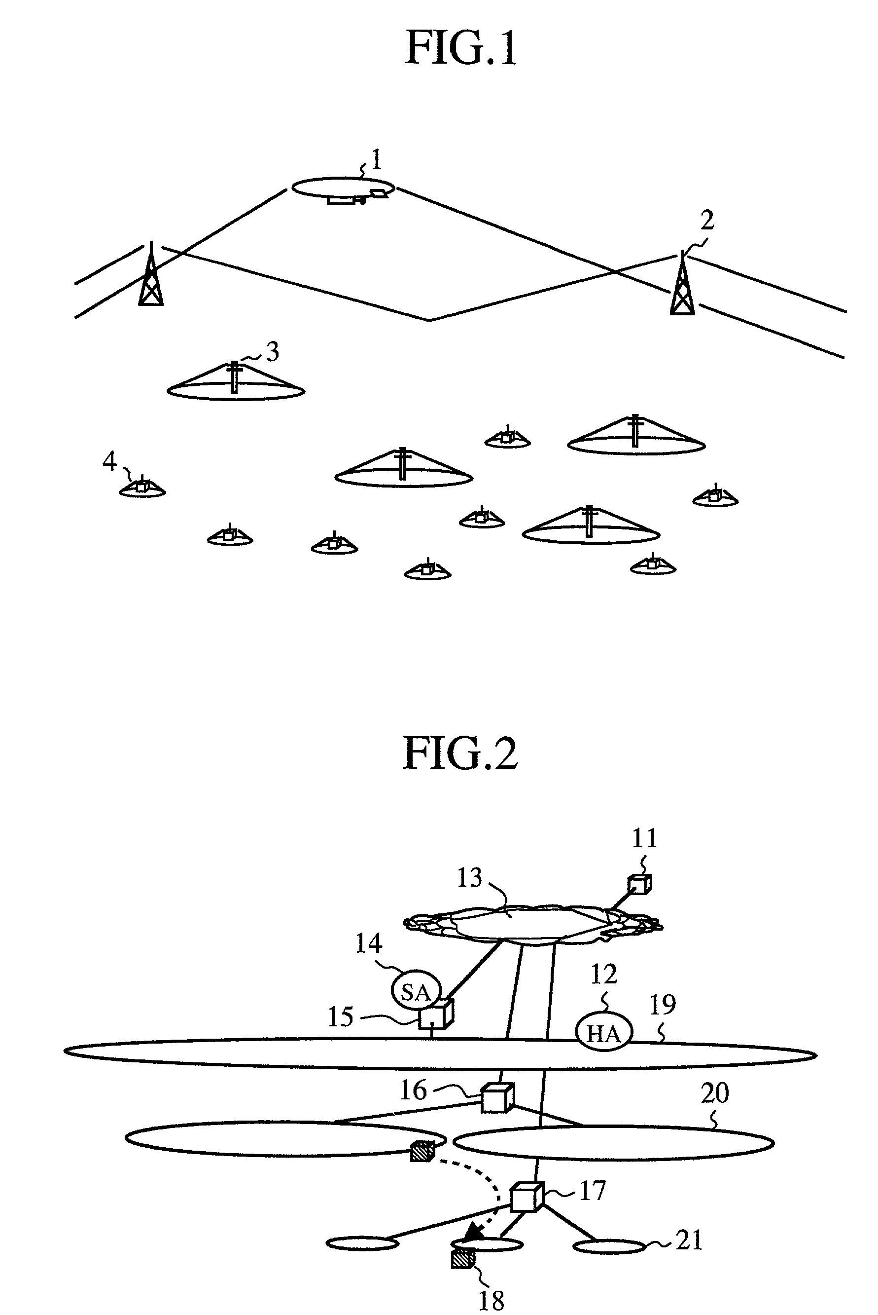
[0052]FIG. 1 is a conceptual diagram showing a radio overlay network to which applied is a radio communication system according to a first embodiment of the present invention. The radio overlay network is constituted of a plurality of radio communication networks that have different characteristics, respectively, such as geographic service coverages, propagation rates, mobility support for terminals, and service charges.

[0053]Reference symbol 1 designates an access point of a stratosphere platform. The service area of the stratosphere platform network may be divided into a plurality of cells. An airship or access point 1 has a cell having a radius of about 50 km. The stratosphere platform network covers the entire service area of the radio overlay network according to the first embodiment. The stratosphere platform network uses millimeter wave for implementing high rate propagation, but the service charge is expensive and the power consumption at radio communication terminals is hig...

second embodiment

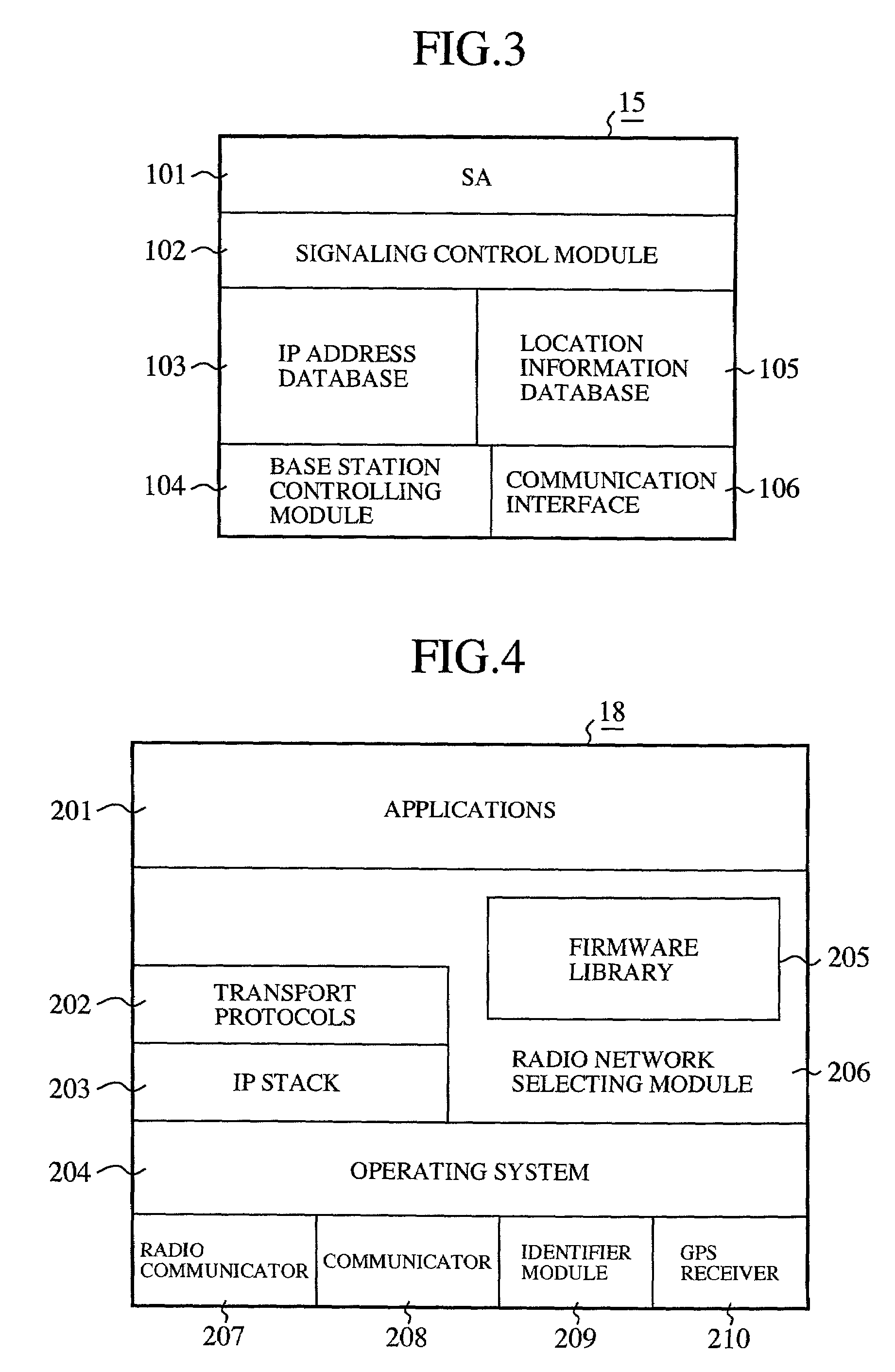
[0121]In a second embodiment of the radio overlay network, when change of sub-network used by the radio communication terminal 18 becomes necessary, the radio network selecting module 206 of the radio communication terminal 18 may inquire of the SA 101 about the sub-networks that can be availed by the radio communication terminal 18. The reason for change of sub-network is, for example, a change of communication requirements indicated by the application used in the radio communication terminal 18, a change of quality of service indicated by the other party (source terminal), or movement of the radio communication terminal 18.

[0122]In the radio communication terminal 18, once the operating system 204 detects a change in communication requirement indicated by the utilized application, it inquires of the SA 101 about available sub-networks. In addition, once the operating system 204 detects that recommended attributes of quality of service indicated by a received IP packet differ from ...

third embodiment

[0128]In the first and second embodiments, the individual sub-networks 19, 20 and 21 constituting the radio overlay network are used for IP communication. However, each of the individual sub-networks has an inherent purpose, e.g., mobile phone network, PHS network, or bidirectional pager network. Moreover, individual radio communication terminals under the radio overlay network include not only terminals specialized for IP communication, but also terminals that can execute inherent purpose and IP communication, such as mobile phone or PHS handsets.

[0129]Some packets are frequently used only in a specific sub-network. For example, packets for mobile phone can be used in mobile phone handsets. It is preferable that discrimination can be made on whether or not a packet is useful in a specific sub-network.

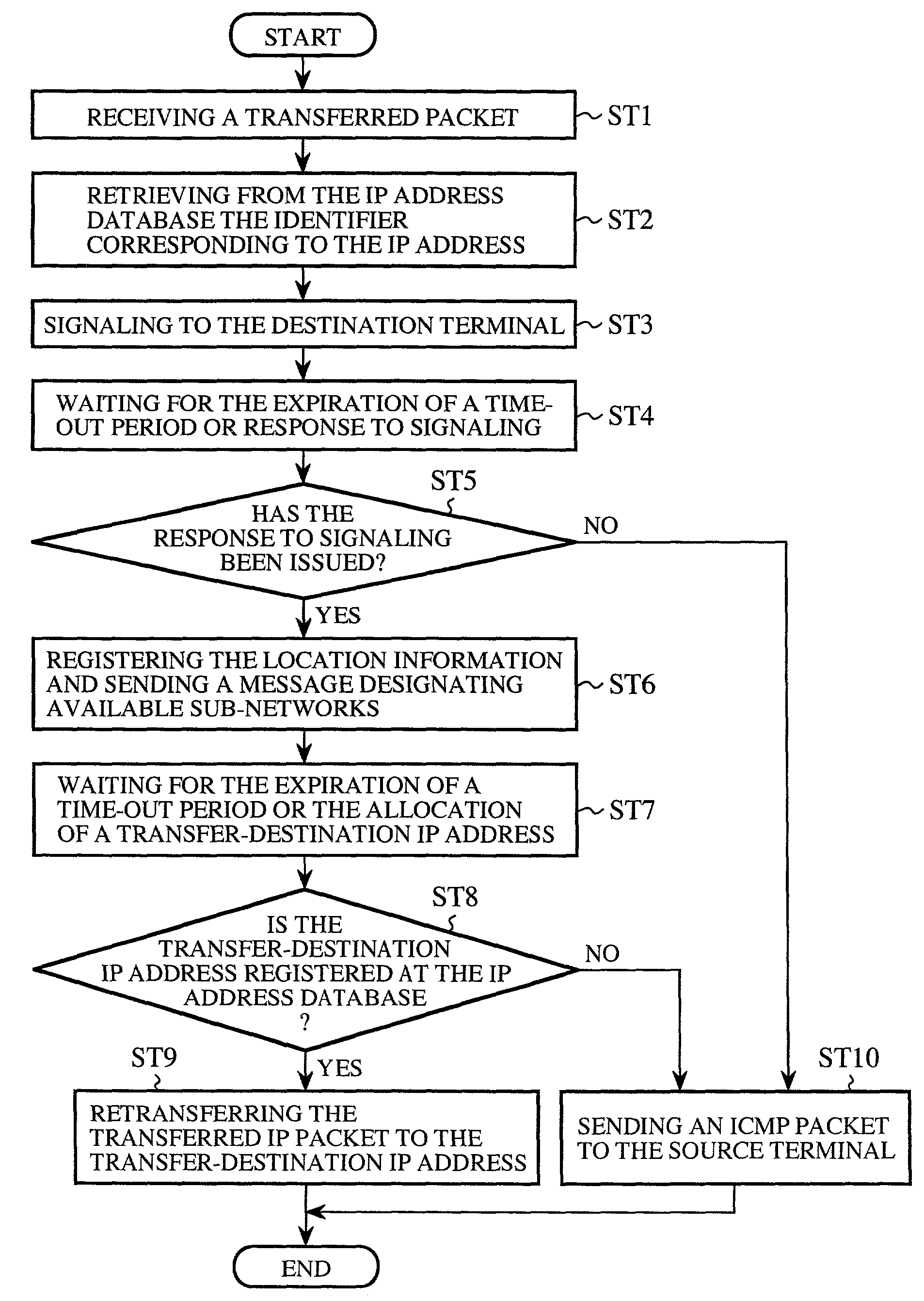
[0130]Accordingly, when an IP packet transferred from the HA 12 is useful in a specific network and includes a designation of sub-network that the destination terminal can avail, the S...


PUM


Abstract

A radio communication control station including a packet receiver, a paging controller, a location information receiver, and a retriever. The packet receiver receives an IP packet destined for a radio communication terminal subscribing to one of sub-networks constituting a composite radio communication network. The paging controller causes one of the sub-networks to page the radio communication terminal. The location information receiver receives location information on a current location of the radio communication terminal from the radio communication terminal. The retriever retrieves candidates of sub-networks that can be employed by the radio communication terminal on the basis of the location information on the radio communication terminal. The radio communication terminal selects a sub-network for its use among from the candidates and establishes an environment for communication with the sub-network.

Description

BACKGROUND OF THE INVENTION[0001]1. Field of the Invention[0002]The present invention relates to a radio communication control station, a radio communication terminal, a home agent, and a radio communication method for implementing IP communication in a composite radio communication network comprising a plurality of radio communication networks.[0003]2. Prior Art[0004]On account of the development of radio communication networks including mobile phone networks and the universalization of the Internet, the demand of Internet communication by means of radio communication terminals is rising. Such a demand has been satisfied, e.g., by i-mode (Trademark of NTT DoCoMo Inc. Tokyo, Japan) and the rapid popularization of i-mode is remarkable in this country.[0005]In accordance with the i-mode technique, however, terminals are not given Internet protocol (IP) addresses, which are terminal identifiers for the Internet. Accordingly, a node on the Internet-side cannot carry out self-initiated t...

Claims


Application Information

Patent Timeline
Patent Type & Authority Patents(United States)
IPC IPC(8): H04Q7/00H04W16/30H04L45/851H04L47/43H04W24/00H04W28/00H04W40/34H04W48/18H04W64/00H04W68/00H04W80/00H04W84/12
CPCH04W48/18H04W80/00H04W68/00H04W64/00
Inventor SAKAKURA, TAKASHI
Owner MITSUBISHI ELECTRIC CORP
Why Eureka
Try Eureka