Directed gas injection apparatus for semiconductor processing

a gas injection apparatus and semiconductor technology, applied in semiconductor/solid-state device testing/measurement, individual semiconductor device testing, instruments, etc., can solve the problems of limited maximum etch rate, inadequate protection, and jeopardizing side-wall profiles, so as to prolong the consumable life and improve the spatial uniformity of flux

Inactive Publication Date: 2006-09-05
TOKYO ELECTRON LTD
View PDF6 Cites 21 Cited by
  • Summary
  • Abstract
  • Description
  • Claims
  • Application Information

AI Technical Summary

Benefits of technology

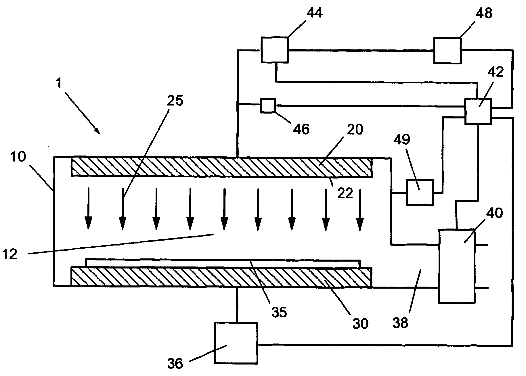
[0015]It is a further object of the present invention to provide a gas injection system design comprising a plurality of gas injection orifices, each of which is arranged relative to one another to improve the spatial uniformity of the flux of chemical species normal to the substrate surface.
[0016]It is another object of the present invention to provide a gas injection system design comprising one or more gas injection orifices, a sensor to monitor an intrinsic gas injection parameter and a controller, the use of which enables monitoring the state of the one or more gas injection orifices. The state of the gas injection orifices can be used to determine consumable replacement and the current state of the gas injection orifices can be used to return the current state to the design state, hence controlling the gas injection orifices and prolonging consumable lifetime.

Problems solved by technology

Hence, conventional practice entails adjusting the plasma density to optimize the concentration of the preferred etch radical to achieve the enumerated conditions above and, in general, for oxide etch it can lead to limitations on the maximum etch rate.
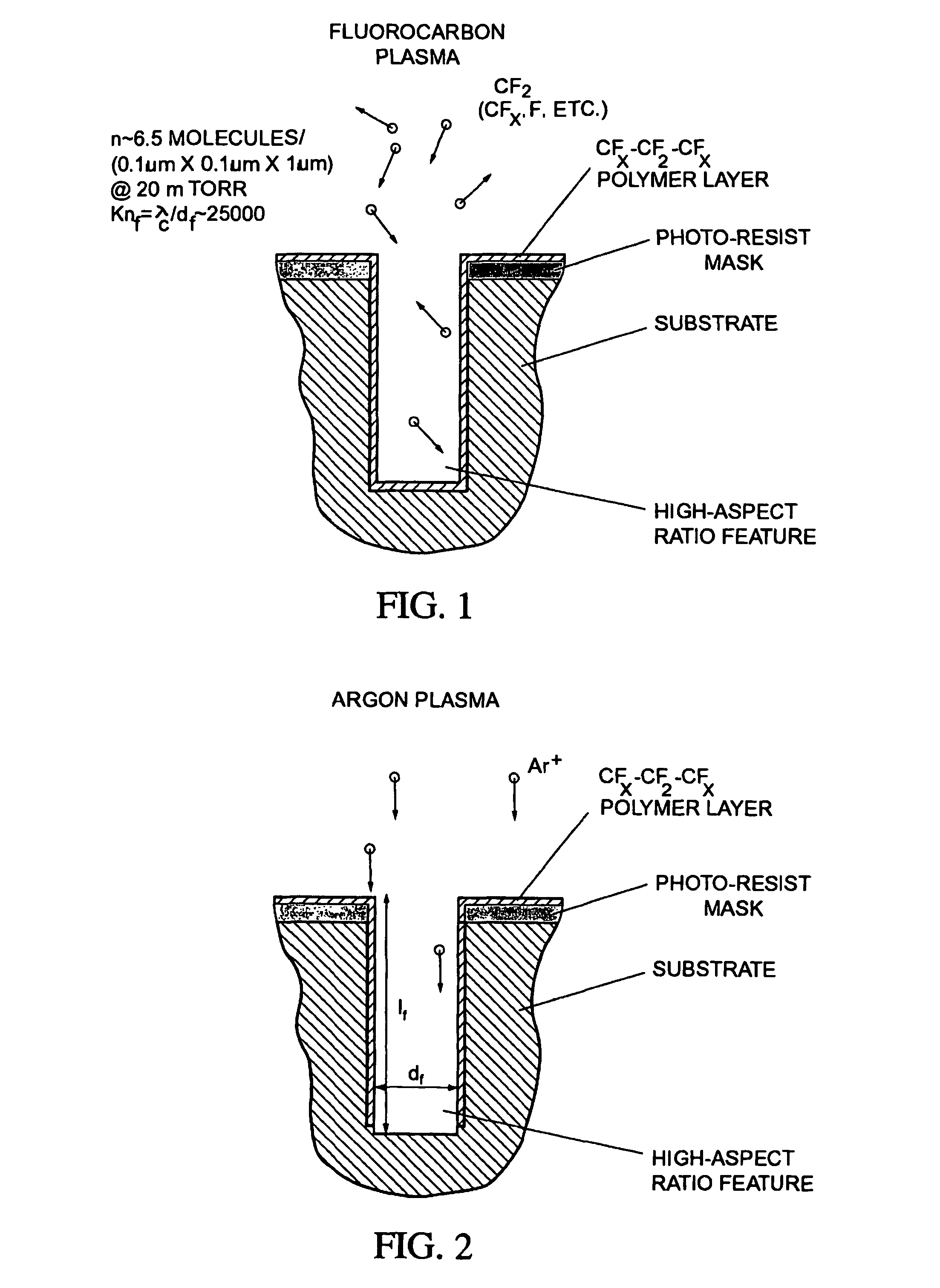
Moreover, inappropriate chemistry due to excessively high dissociation rates can lead to inadequate protection of feature side-walls and therefore jeopardize side-wall profiles leading to an isotropic etch.
Lastly, insufficient plasma density and low dissociation (i.e., high concentrations of CF3, CF2, etc.) can lead to etch stop due to material (i.e., C) build-up at the bottom of etch features.
Furthermore, conventional systems suffer from a lack of control of the gas injection orifice discharge coefficient.
Conventional systems do not monitor the state of a “consumable” gas injection system nor do they attempt to control the gas injection properties to prolong the life of a “consumable” gas injection system.
In addition to gas injection orifices with an uncontrollable discharge coefficient, conventional designs suffer from an additional shortcoming.

Method used


Image

  • Directed gas injection apparatus for semiconductor processing
  • Directed gas injection apparatus for semiconductor processing
  • Directed gas injection apparatus for semiconductor processing

Examples


second embodiment

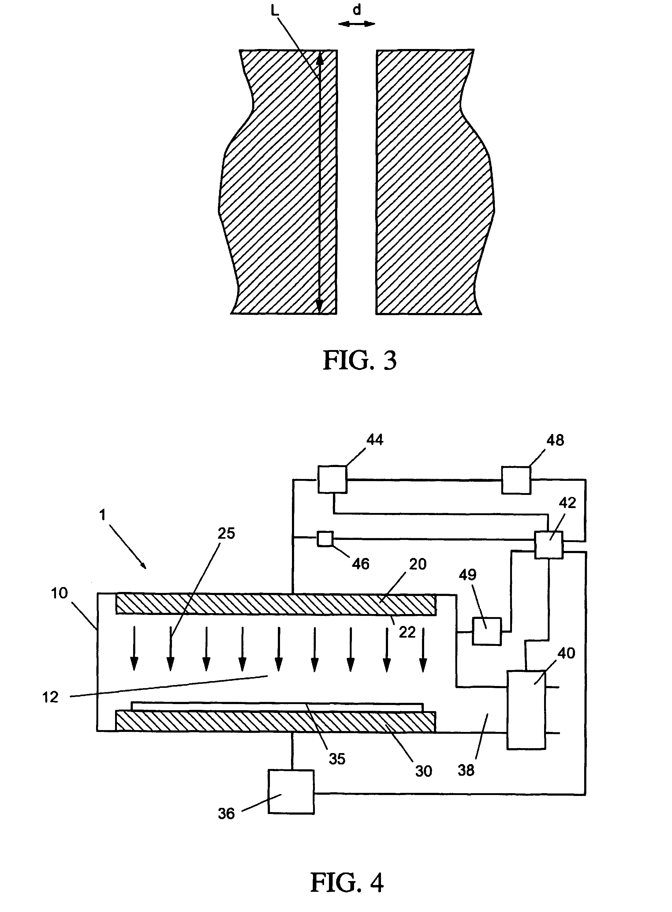
[0038]FIG. 5B illustrates a cross-section of an inject orifice, namely a divergent nozzle. The divergent nozzle includes a throat 45 of diameter d (e.g., d is on the order of 0.025 to 0.5 mm) and a corresponding aspect ratio L / d45 of diameter d to the exit 85 of diameter de with an exit diameter ratio de / d on the order of 4. The purpose of the conical section is to restrain the rate at which the gas expands into the low pressure environment. In general, the angle β indicated as 90 in FIG. 5B should not exceed approximately 18 degrees in order to minimize radial flow losses and possibly deter flow separation from the nozzle walls. In addition, a small angle can lead to excessive nozzle lengths for a given area ratio as well as increased friction losses. The angle 90 is preferably 50.005 and one would choose the divergent nozzle when KnMolecular gas dynamics and the direct simulation of gas flows, Clarendon Press, Oxford (1994).

third embodiment

[0039]In a third embodiment, shown in FIG. 5C, the inlet 65, entry region with walls 70 and throat entry wall 75 are removed, and the gas injection orifice is fabricated within a piece of material of thickness equivalent to the length L of wall 50 (or throat 45). The embodiment described in FIG. 5C is hereinafter referred to as a simple orifice.

[0040]In summary, the difference in gas orifice geometry between (1) a showerhead orifice and (2) a shaped orifice or nozzle (e.g., a sonic orifice or a divergent nozzle) leads to significantly different flow conditions.

[0041]FIG. 6 presents the measured discharge coefficient versus the orifice Knudsen number Kn. The orifice Knudsen number represents the ratio of the mean free path at total (or stagnation) conditions to the throat diameter d. Note that Kn1 signifies the free molecular flow regime. Clearly, the discharge coefficient is significantly larger for an aspect ratio of L / d=0.5 versus and aspect ratio L / d=20 (by a factor of 4 to 5), f...


PUM

PropertyMeasurementUnit
lengthaaaaaaaaaa
diameteraaaaaaaaaa
throat diameteraaaaaaaaaa

Abstract

A method and system for utilizing a gas injection plate comprising a number of shaped orifices (e.g., sonic and simple orifices, and divergent nozzles) in the gas inject system as part of a plasma processing system. By utilizing the shaped orifices, directionality of gas flow can be improved. This improvement is especially beneficial in high aspect ratio processing.

Description

CROSS-REFERENCE TO RELATED APPLICATIONS[0001]This application is related to co-pending application Ser. No. 60 / 272,452, filed Mar. 2, 2001 entitled “SHOWER-HEAD GAS INJECTION APPARATUS WITH SECONDARY HIGH PRESSURE PULSED GAS INJECTION” and co-pending application Ser. No. 60 / 301,413, filed on Jun. 29, 2001 entitled “DIRECTED GAS INJECTION APPARATUS FOR SEMICONDUCTOR PROCESSING”. This application is also related to and claims priority to co-pending application Ser. No. 60 / 301,436, filed on Jun. 29, 2001. The contents of those applications are incorporated herein by reference.BACKGROUND OF THE INVENTION[0002]1. Field of the Invention[0003]The present invention is directed to a method and system for utilizing a shaped orifice or nozzle in a plasma processing system.[0004]2. Discussion of the Background[0005]During the fabrication of integrated circuits (IC), a conventional approach to oxide etch employs a capacitively coupled plasma (CCP) source, wherein a process gas comprising argon, ...

Claims


Application Information

Patent Timeline
Patent Type & Authority Patents(United States)
IPC IPC(8): G06F19/00H01L21/3065H01J37/32H01L21/00
CPCH01L21/67017H01J37/3244
Inventor STRANG, ERIC J.
Owner TOKYO ELECTRON LTD
Why Eureka
Try Eureka