Cooling chamber and system of a cooling chamber with a microtome

a cooling chamber and microtome technology, applied in the field of cooling chambers with microtomes, can solve the problems of ice crystals, no longer flowing cold gas steadily, interference with manipulation, etc., and achieve the effect of reliable cutting section handling

Active Publication Date: 2006-09-12
LEICA MICROSYSTEMS GMBH
View PDF8 Cites 8 Cited by
  • Summary
  • Abstract
  • Description
  • Claims
  • Application Information

AI Technical Summary

Benefits of technology

[0008]It is therefore the object of the present invention to create a cooling chamber with which optimum illumination and reliable handling of cut sections is possible.
[0010]It is a further object of the invention to create system a cooling chamber with a microtome or ultramicrotome with which optimum illumination and reliable handling of the cut sections is possible.
[0012]The use of light-emitting diodes as the illumination system has the advantage that they emit only a small amount of heat and therefore cause no turbulence in the nitrogen gas. Light-emitting diodes have a small emission angle. Several light-emitting diodes can illuminate the knife in directed fashion, and result in a high intensity. Good visibility of the cut sections with the stereomicroscope is thus achieved at high magnifications. Depending on the arrangement and segmentation of the light-emitting diodes, the cut sections can be illuminated both laterally and perpendicularly. Operation of segments of the arrangement of light-emitting diodes makes possible, for example, oblique illumination or only frontal illumination. It has been found that light-emitting diodes are functional down to a temperature of approximately −160° C. The arrangement according to the present invention of the light-emitting diodes in the cooling chamber ensures that the temperature does not fall below this value.

Problems solved by technology

The illumination using a fiber optic system, on the other hand, can be brought very close to the knife and has sufficient intensity, but on the one hand it interferes with manipulation when the sections are removed from the knife, and on the other hand illumination with the fiber optic system causes ice crystals.
These objects introduce heat into the cold region and cause turbulence, and the cold gas no longer flows out steadily.
Turbulence at the boundary layer with the moist air results in the precipitation of small ice crystals, which then also settle on the knife and reduce the service life of a knife between cleanings.

Method used


Image

  • Cooling chamber and system of a cooling chamber with a microtome
  • Cooling chamber and system of a cooling chamber with a microtome
  • Cooling chamber and system of a cooling chamber with a microtome

Examples


Embodiment Construction

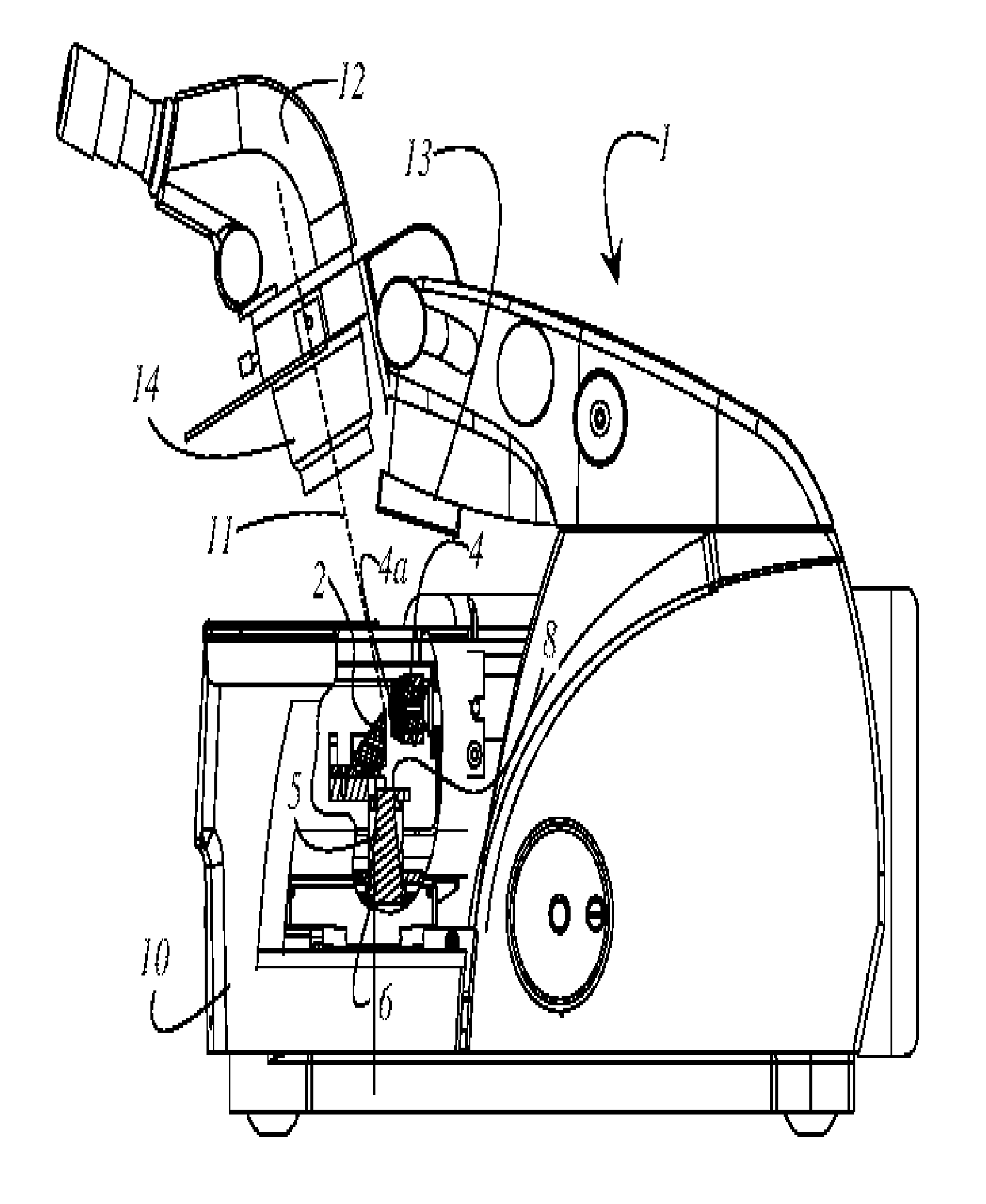
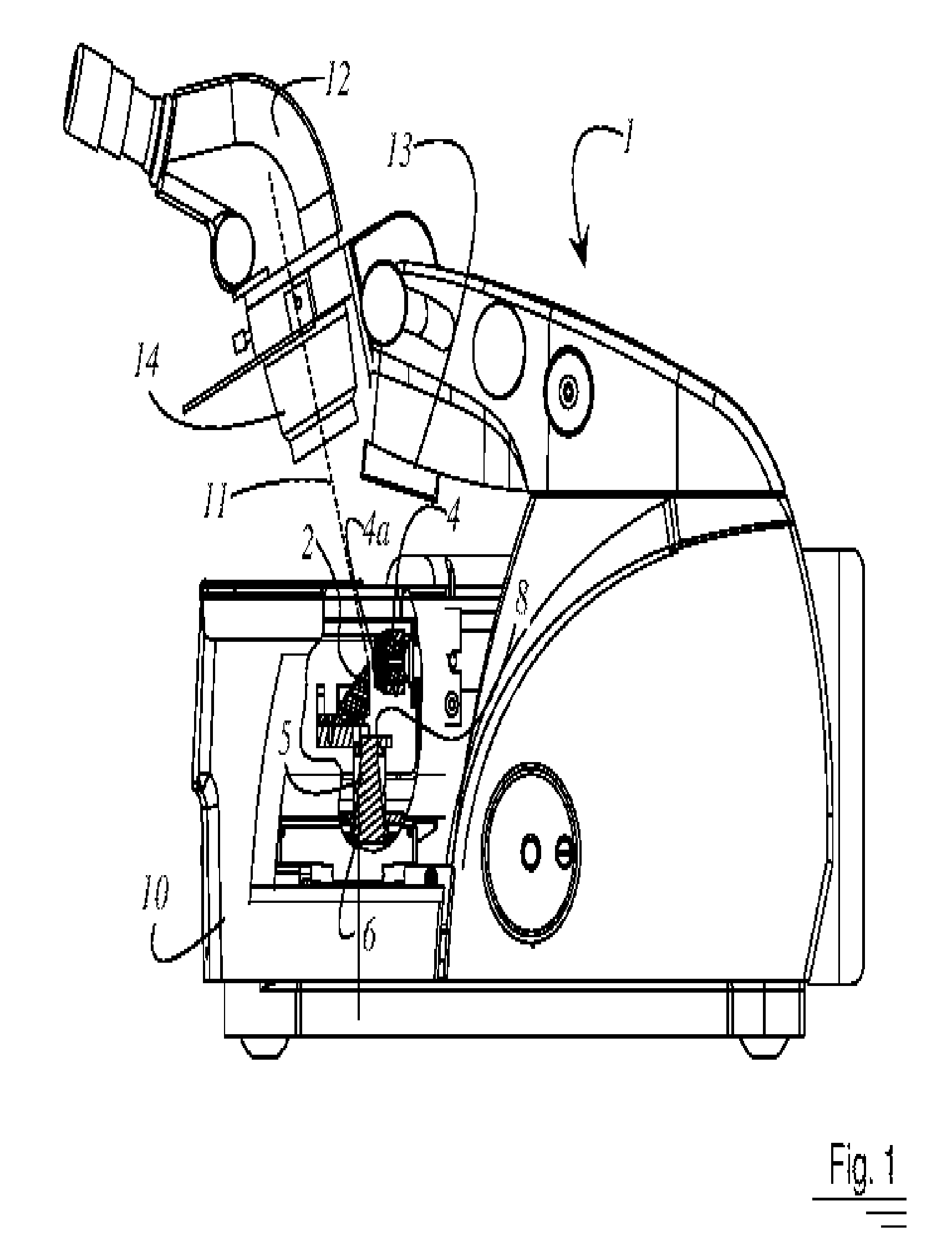
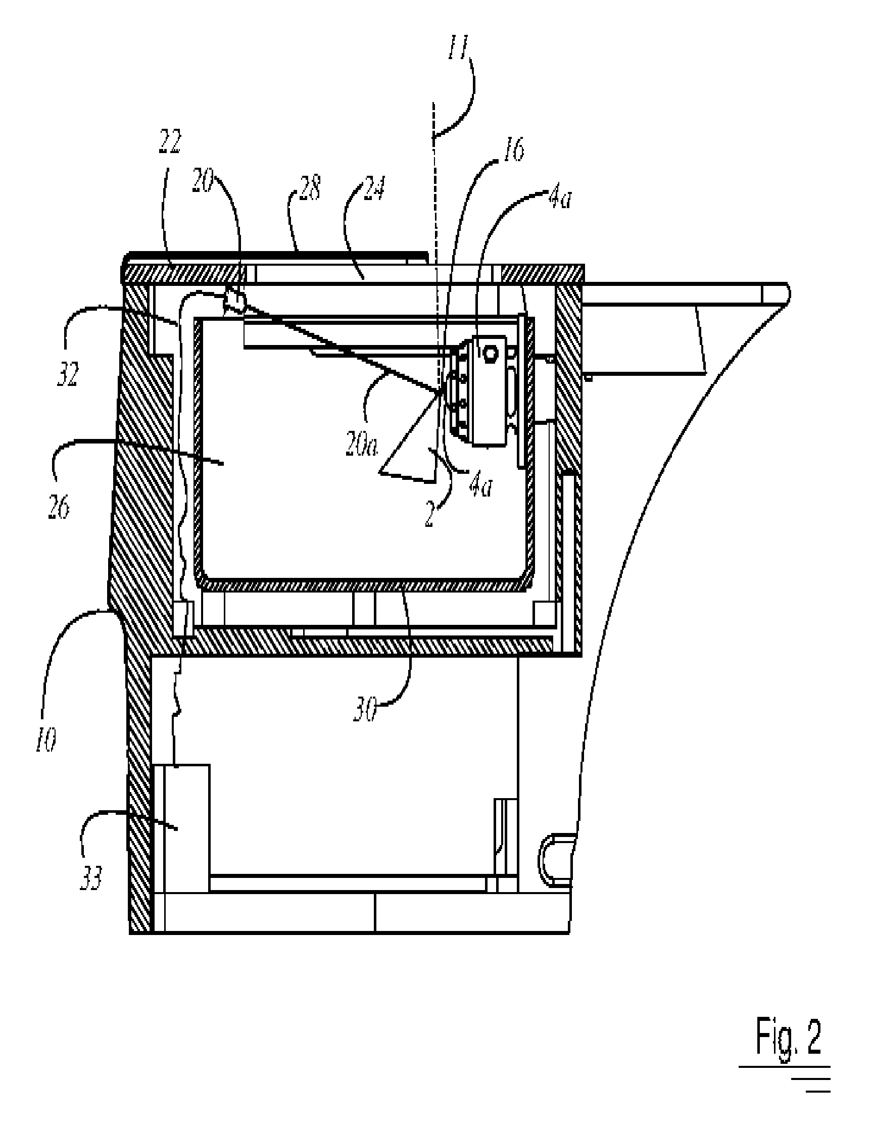
[0020]FIG. 1 is a side view of a microtome or ultramicrotome 1 having a cooling chamber 10. Parts of cooling chamber 10 are omitted in order to elucidate the association between at least one knife 2 and sample holder 4. The at least one knife 2 is inserted into a knife holder 5. Knife holder 5 is arranged with respect to a base-mounted illumination system 6 in such a way that exit opening 8 of base-mounted illumination system 6 is positioned below knife 2, which is currently in the working position. The working position is defined by the fact that knife 2 is arranged opposite sample holder 4. In the working position, thin sections can be produced with knife 2 from a sample 4a that is clamped in sample holder 4. Base-mounted illumination system 6 is used to achieve an optimum adjustment in the presetting operation between knife 2 and sample 4a. An incident illumination system 13 for cooling chamber 10 is also provided on microtome 1.

[0021]Microtome 1 is equipped with a stereomicrosco...


PUM

PropertyMeasurementUnit
temperatureaaaaaaaaaa
opticalaaaaaaaaaa
optical axisaaaaaaaaaa

Abstract

A cooling chamber 10 for a microtome 1 is disclosed. A knife 2 having a cutting edge 16 is arranged in the cooling chamber 10 opposite a sample holder 4 having a sample 4a retained therein. The microtome 1 further possesses a stereomicroscope 12 having an optical system 14, the optical system 14 defining an optical axis 11. The region of the sample 4a and of the cutting edge 16 of the knife 2 is observable with the stereomicroscope 12. There is mounted in the cooling chamber 10 an illumination system 20 that emits light 20a and is directed onto a surface 2a of the knife 2 in such a way that the light 20a reflects from the surface 2a parallel to the optical axis 11.

Description

CROSS REFERENCE TO RELATED APPLICATIONS[0001]This application claims priority of the German patent application 103 46 996.6, filed Oct. 7, 2003, which is incorporated by reference herein.FIELD OF THE INVENTION[0002]The invention concerns a cooling chamber for a microtome. Additionally the invention concerns a system of a cooling chamber with a microtome.BACKGROUND OF THE INVENTION[0003]The microtome with the designation Leica Ultracut UCT, on which the Leica FCS cooling chamber is mounted, has two illumination systems as standard equipment. Fluorescent lamps are mounted outside the chamber next to the objective of the stereomicroscope, and serve to illuminate the cut sections. The second illumination system is positioned, by means of light guides, directly beneath the knife. The bright gap produced by this illumination is helpful as the knife and specimen are brought close to one another.[0004]The model MTX and MTXL microtome of the RMC company has an illumination system that is equ...

Claims


Application Information

Patent Timeline
Patent Type & Authority Patents(United States)
IPC IPC(8): F21V33/00G01N1/06G01N1/42G02B21/28
CPCG01N1/06G02B21/28G01N1/42Y10S362/80G01N2001/068Y10T83/828Y10T83/283
Inventor LIHL, REINHARDTANKI, SIEGFRIEDZIMMERMANN, MICHAEL
Owner LEICA MICROSYSTEMS GMBH
Why Eureka
Try Eureka