Milling disk for a floor machining appliance

a technology of floor machining and grinding disk, which is applied in the direction of milling equipment, maintenance and safety accessories, cutting machines, etc., can solve the problems of reducing the service life of the reversible metallic carbide disk. , to achieve the effect of facilitating the removal of swarf or chips

Active Publication Date: 2006-09-12
EUGEN LAEGLER
View PDF20 Cites 33 Cited by
  • Summary
  • Abstract
  • Description
  • Claims
  • Application Information

AI Technical Summary

Benefits of technology

[0005]In order to achieve these and / or other objects appearing from the present specification, claims and drawings, in the present invention the milling means are constituted by ceramic cutting tips. The ceramic cutting tips are able to cope with heavier loads than metallic carbide cutting tips and more particularly they are tougher. The cutting edges of the ceramic cutting tips are subject to substantially less wear than those of metallic carbide cutting tips. One design of the ceramic cutting tips as reversible ceramic cutting tips, for example in the form of cuboid cutting tips, leads to the convenient possibility of repeated use of the cutting tips. For instance, the cuboid ceramic cutting tips have eight cutting faces.
[0009]Preferably at least two of the milling means mounts are arranged at a different radial distance from the center of rotation of the milling disk. It is more especially preferred for several, that is to say at least two, milling means mounts to be arranged along a row line adjacent to each other. Such row or in-line arrangements are preferably distributed in a stellate manner over the bottom face of the milling disk, something apt to lead to smooth running of the milling disk.
[0011]It has turned out to be advantageous if the row axis or line of an in-line extends at an angle to a radial line so that during operation of the milling disk one ceramic cutting tip, which is farther removed for the center of rotation, will bite into the substructure to be worked before a ceramic cutting tip, which is nearer the center of rotation of the milling disk. The milling means mounts, which is radially to the outside in the operating direction of the rotary disk, will be nearer the radial line than a radially inner milling means mounts. This design favors handling of the floor machining appliance. It will be clear that a reversed design is possible, in the case of which the ceramic cutting tip farther to the outside will cut into the substructure after the ceramic cutting tip which is farther inward, something which favors removal of swarf or chips.
[0012]Furthermore, it is preferred for the ceramic cutting tips to be so obliquely held by the milling means mounts that the cutting edges of the ceramic cutting tips are oblique in relation to a radial line on the milling disk. It is preferred for the cutting edge to be farther removed from a radial line nearer the center of the disk than farther outward. This measure among other things contributes to satisfactory removal of swarf.
[0017]One or more milling means mounts are in this case arranged on an interchangeable carrying element, an in-line arrangement of the milling means mounts on the carrying element being preferred. On the milling disk a plurality of carrying elements are present, on which the interchangeable carrying elements may be arranged. It is in this manner that a plurality of ceramic cutting tips may be arranged on the milling disk with a simple design. The carrying element may be fitted with new ceramic cutting tips while removed from the milling disk or, respectively, the ceramic cutting tips may be turned over while removed from the milling disk so that the milling disk may be furthermore operated with the ceramic cutting tips still on it. The carrying element mounts are preferably distributed peripherally about the milling disk, it being preferred to have equal radial angles between the carrying element mounts. For instance a stellate arrangement of the carrying element mounts is advantageous.
[0024]The milling disk preferably essentially comprises oxidation-resistant material, more particularly stainless steel. This renders possible simple cleaning of the milling disk, for example in a solvent bath, in water or the like.

Problems solved by technology

It has turned out to be a disadvantage that such reversible metallic carbide disks are subject to rapid wear in many applications, their cutting edges becoming blunt or scored or the like.

Method used


Image

  • Milling disk for a floor machining appliance
  • Milling disk for a floor machining appliance
  • Milling disk for a floor machining appliance

Examples


Embodiment Construction

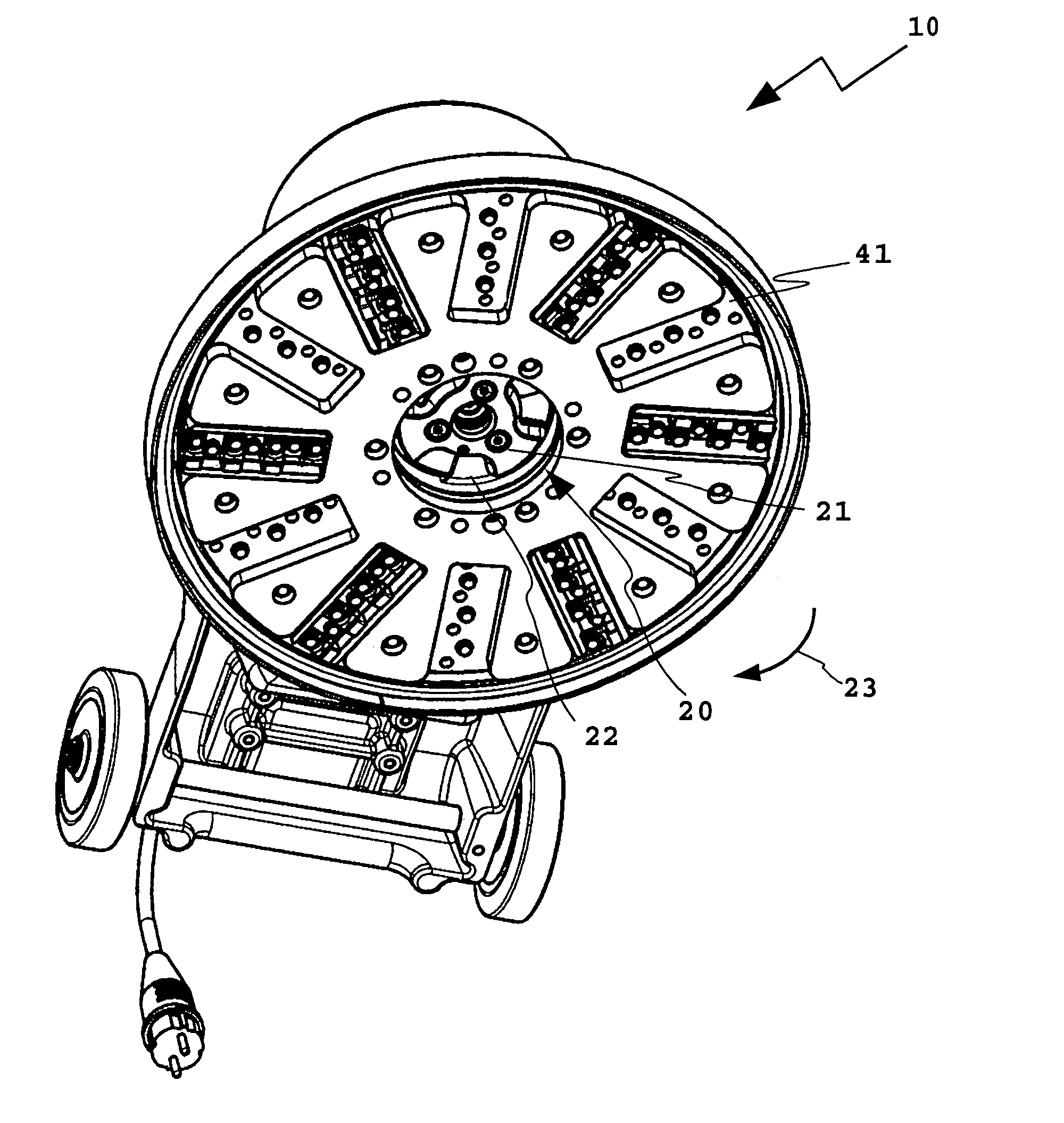
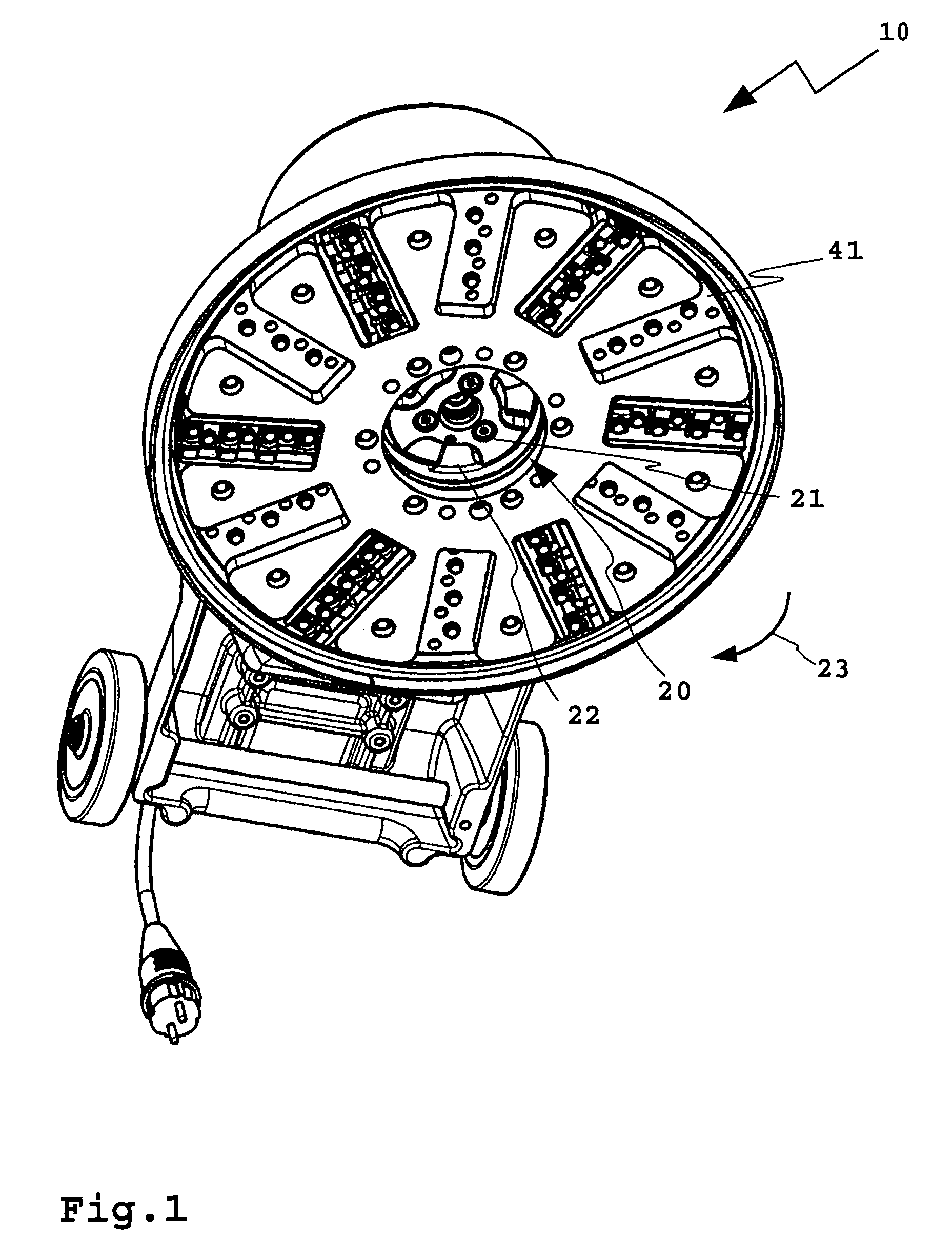
[0038]A floor machining appliance 10 for a floor 11 possesses a milling disk 12 at the bottom, such disk being driven by a drive 13, as for example an electric motor in rotation. The drive 13 is supplied with electric power by way of a cable 14. The milling disk 12 is moved essentially in parallelism to the substructure 11 or floor. For operator movement of the floor machining appliance 10 there is a rod-like guide means 15, which is arranged on a base part 16 pivotally (indicated by an arrow 17). At the top, free end of the guide means 15 a handle 18 is arranged. On the handle 18 there are one or more electrical switches for switching the drive 13 on and off. The safety orientated switching means 19 is in the form of a switching means provided for example with a switching instrumentality requiring operation with both hands. Moreover here the machine possesses a setting lever (not illustrated) for releasing and / or arresting the pivotal motion of the guide means 15.

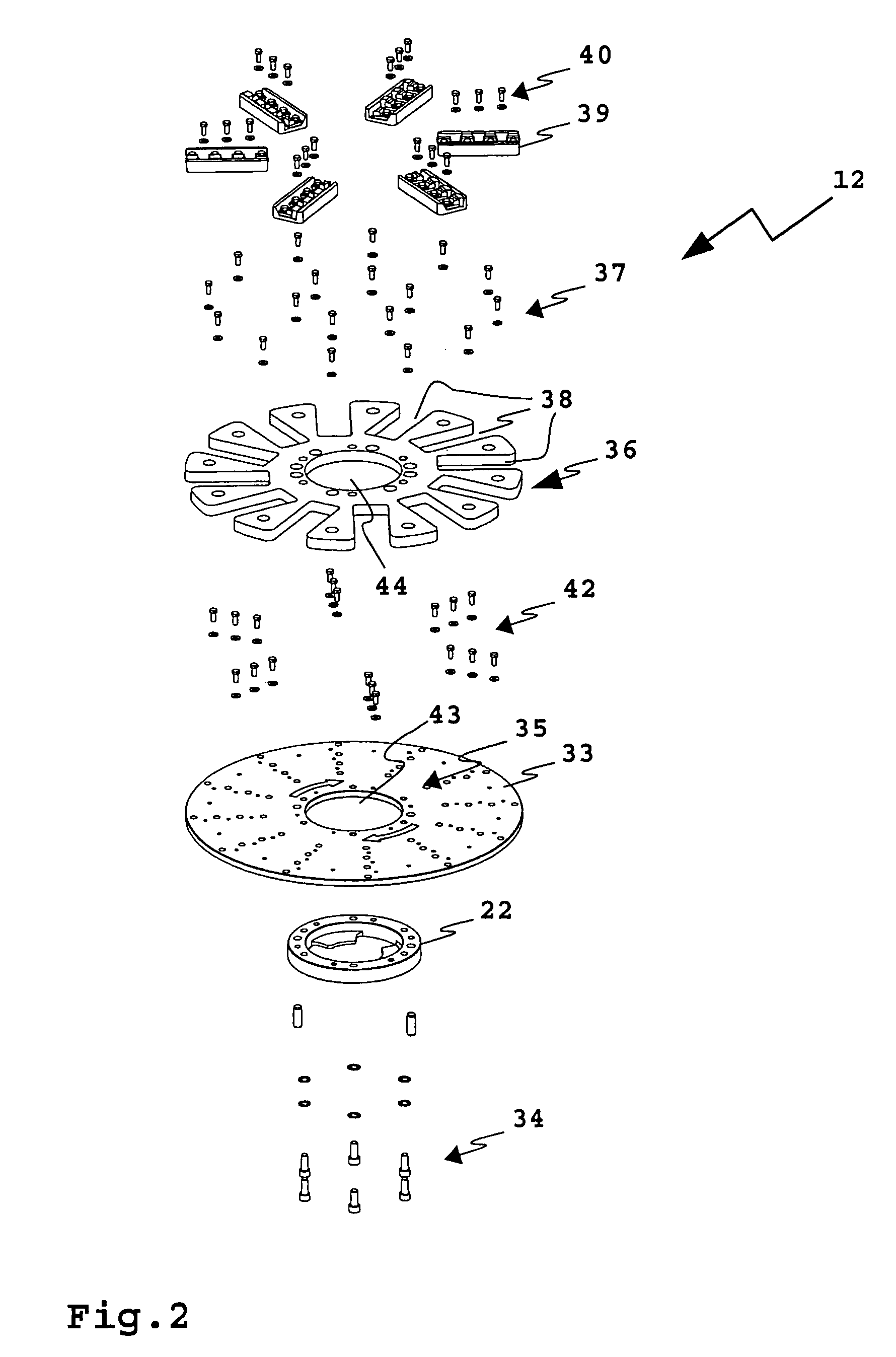
[0039]The milling ...


PUM

PropertyMeasurementUnit
weightaaaaaaaaaa
angleaaaaaaaaaa
radial distancesaaaaaaaaaa

Abstract

A milling disk for a floor machining appliance has a plurality of mounts for holding interchangeable plate-like milling tips, the milling disk being driven for rotation by the floor machining appliance and being held substantially parallel to the substructure to be machined so that the milling tips may bite into the substructure and remove matter from the surface thereof. The milling tips are constituted by ceramic cutting tips.

Description

BACKGROUND OF THE INVENTION[0001]The invention relates to a milling disk for a floor machining appliance comprising a plurality of milling means mounts for interchangeable disk-like milling means, such milling disk being driven for rotation thereof during operation by the floor machining appliance and being moved essentially parallel to the substructure to be machined so that the milling means may bite into the substructure and machine away the surface thereof. Moreover, the invention relates to a floor machining appliance having such a milling disk.THE PRIOR ART[0002]Floor machining appliances may be adapted for different applications. For instance, for stripping off parquet material a disk is arranged on the floor machining appliance on which sanding disks of sandpaper are attached. Furthermore brush disks with bristles of natural hair or wire brushes may be employed with the floor machining appliance. For the preparation of substructures or underfloors, for example for the remova...

Claims


Application Information

Patent Timeline
Patent Type & Authority Patents(United States)
IPC IPC(8): B23C1/20B23C3/00B23C5/20B27C1/00B27G13/10
CPCB27C1/005B27G13/10Y10T407/1962Y10T407/27Y10T407/1944Y10T409/306552Y10T407/1932Y10T407/1926Y10T407/1922Y10T409/304312Y10T407/191Y10T409/309408
Inventor LAGLER, KARLEUGEN
Owner EUGEN LAEGLER
Why Eureka
Try Eureka