Coaxial cable

a technology of coaxial cable and cable, which is applied in the direction of power cables, cables, insulated conductors, etc., can solve the problems of disturbance of picture signals, noise amplification, and inability to obtain clear images, so as to prevent attenuation of picture signals, simple system, and strong noise shielding

Inactive Publication Date: 2006-09-12
YOSHO
View PDF9 Cites 8 Cited by
  • Summary
  • Abstract
  • Description
  • Claims
  • Application Information

AI Technical Summary

Benefits of technology

[0018]In the present invention, by virtue of the above described constitution, in the part surrounded by a first conductor which is on the concentric circle having a central conductor of the coaxial cable as its center and a second conductor which is outside of the first conductor, a noise barrier zone which is an electro-magnetically active field where the magnetic fields constantly cancel each other out is formed. The intrinsic noise shielding effect of the shield is added so as to produce an extremely strong noise shielding effect. Therefore, according to the coaxial cable of the present invention, external noises can be completely shut out, a cable compensator or the like for preventing attenuation of picture signals can be reduced, a simple system can be composed, and picture signals under no influence of noises can be transmitted over a long distance. In addition, considerable economic effects are brought about.

Problems solved by technology

Noises caused by such external factor are known to be a cause of the attenuation of picture signals and disturbance of picture signals.
However, when cable compensators amplify attenuated picture signals, a phenomenon is caused in which noises are amplified at the same time.
However, on the contrary, when cable compensators are overused, the result is that clear images cannot be obtained because of noises.
However, there has been a problem for practical use regarding, among external noises, the influence of, for example, high frequency noises having steep wave forms generated when an accelerator of an electric system of an engine, for example, a motorcycle is suddenly stomped on.
Also, in regard to image transmission, there has been a problem for practical use regarding how far a distance clear images having no attenuation can be transmitted without employing cable compensators.

Method used


Image

  • Coaxial cable
  • Coaxial cable
  • Coaxial cable

Examples


second embodiment

[0036]FIG. 4 is a schematic view of a coaxial cable according to the present invention. In FIG. 4, the numbers which are the same as those in FIG. 1 are denoted by the same reference numerals, and explanations thereof are omitted. As shown in FIG. 4, 31 denotes a first conductor on an outer circumference concentric with respect to the central conductor 2, 41 denotes a second conductor positioned on an outer circumference concentric to the central conductor 2 and outside the first conductor 31, and 8 denotes a DC voltage source which applies a predetermined DC voltage between the first conductor 31 and the second conductor 41 in order to cause direct current having a desired current value to flow through the first conductor 31 and the second conductor 41. The first conductor 31 and the second conductor 41 each consist of a metal plate cylindrically wound up. As shown in FIG. 4, the ends of each cylindrically-shaped plate do not necessarily touch, so that there is a gap between the lo...

third embodiment

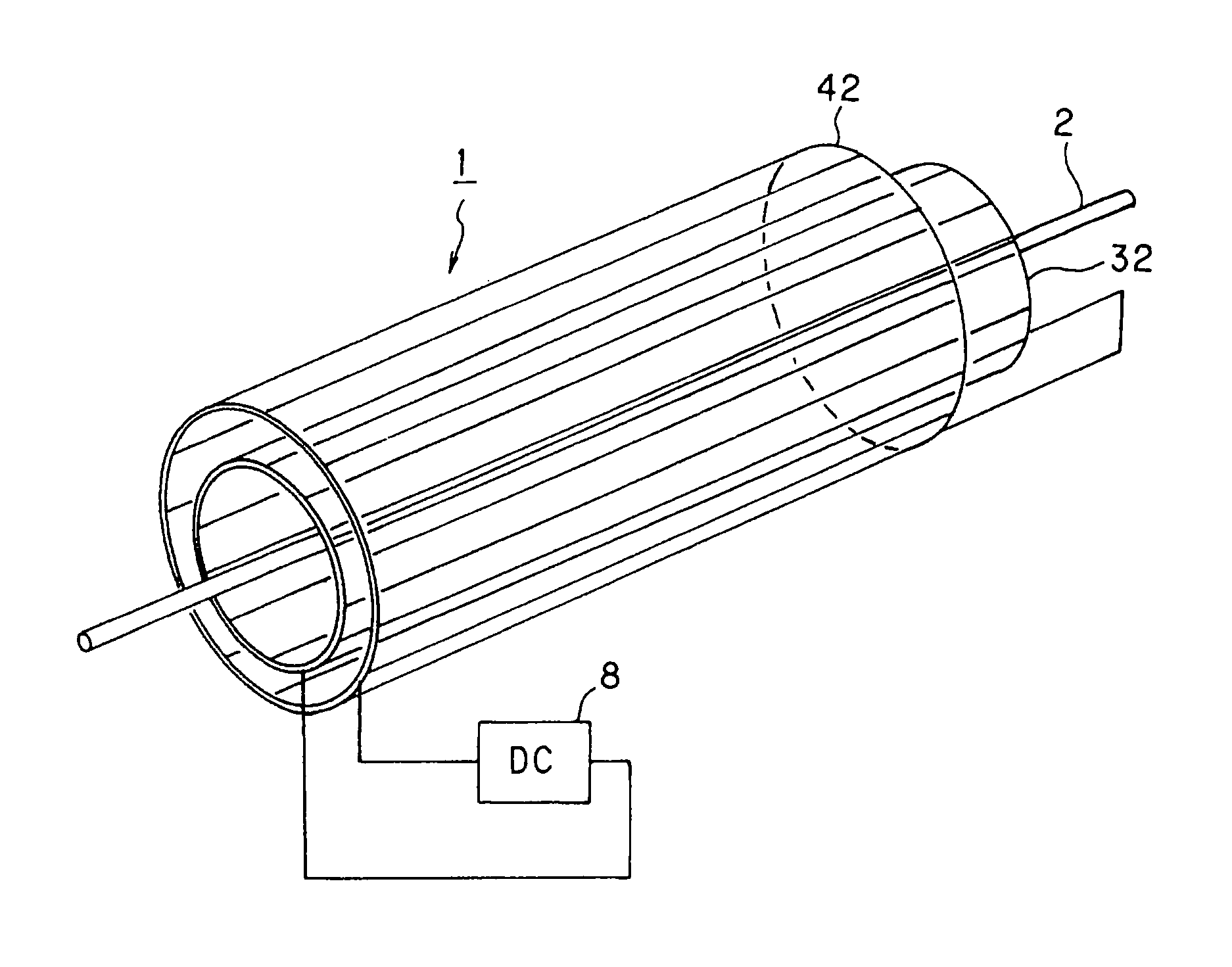
[0038]FIG. 5 is a schematic view of a coaxial cable according to the present invention. In FIG. 5, the numbers which are the same as those in FIG. 1 are denoted by the same reference numerals, and explanations thereof are omitted. As shown in FIG. 5, 32 denotes a first conductor arranged on a circumference concentric to a central conductor 2, 42 denotes a second conductor positioned on an outer circumference concentric with respect to the central conductor 2 and outside the first conductor 31, and 8 denotes a DC voltage source which applies a predetermined DC voltage between the first conductors 32 and the second conductors 42 in order to cause direct current having a desired current value to flow in the first conductors 32 and the second conductors 42. As shown in FIG. 5, the first conductor 32 and the second conductor 42 each consist of a plurality of parallel elongated metal conductor elements electrically connected at both sides. The elongated conductor elements are arranged sid...

fourth embodiment

[0040]FIG. 6 is a schematic view of a coaxial cable according to the present invention. In FIG. 6, the numbers which are the same as those in FIG. 1 are denoted by the same reference numerals and explanations thereof are omitted. A first conductor which is wound around an outer circumference so as to be concentric with respect to a central conductor 2 is denoted by 33, 43 denotes a second conductor wound around the outer circumference so as to be concentric with respect to the central conductor 2 and outside the first conductor 33, and 8 denotes a DC voltage source which applies DC voltage between the first conductor 33 and the second conductor 43 in order to cause direct current having a desired current value to flow in the first conductor 33 and the second conductor 43. The first conductor 33 and the second conductor 43 consist of metal conductors wound spirally around the central conductor 2. The illustrations of a first insulator on the outer circumference of the central conduct...


PUM

PropertyMeasurementUnit
voltageaaaaaaaaaa
impedanceaaaaaaaaaa
frequencyaaaaaaaaaa

Abstract

A first conductor is provided on an outer circumference of a central conductor with an insulator therebetween, a second conductor is provided on a concentric circle having the central conductor as its center and outside the first conductor with an insulator therebetween. A coaxial cable is formed by coating the outside of the second conductor, which is on the concentric circle having the central conductor as its center, with an insulating external coating. A DC voltage source is able to apply DC voltage having a predetermined voltage value between the first conductor and the second conductor such that the direct current flowing in the first conductor and the second conductor takes a desired value. A noise barrier zone formed by the electro-magnetic action of the desired current is formed in the part surrounded by the first conductor and the second conductor on the outer circumference of the central conductor.

Description

BACKGROUND OF THE INVENTION[0001]1. Field of the Invention[0002]The present invention relates to a coaxial cable, and more particularly relates to a coaxial cable in which a central conductor is used for transmitting images. A first conductor and a second conductor, which is outside the first conductor, are provided on the circumference of concentric circles having the central conductor as their center.[0003]2. Description of Related Art[0004]For transmitting images, coaxial cables having characteristic impedance of 75 Ω (ohms) are generally employed. It is known that the attenuation of picture signals is phenomenally approximated by, roughly, one-half power of the frequency. The disclosed measured values, for example, in a 3C-2V coaxial cable: when the frequency of the picture signal is 4 MHz, the attenuation is 27 dB / Km; when the frequency of the picture signal is 6 MHz, the attenuation is 32 dB / Km; when the frequency of the picture signal is 8 MHz, the attenuation is 38 dB / Km; an...

Claims


Application Information

Patent Timeline
Patent Type & Authority Patents(United States)
IPC IPC(8): H01B7/00H01B7/18
CPCH01B11/1813H01B11/183
Inventor ABE, CHIAKI
Owner YOSHO
Why Eureka
Try Eureka