Device of micro vortex for ferrofluid power generator

a technology of ferrofluid and micro vortex, which is applied in the direction of machines/engines, nuclear engineering, and positive displacement liquid engines, etc., can solve the problems of requiring high precision, difficult maintenance, and repair of prior art electrical generators, and achieve the effect of enhancing the efficiency of electric power generation

Inactive Publication Date: 2006-09-12
IND TECH RES INST
View PDF11 Cites 18 Cited by
  • Summary
  • Abstract
  • Description
  • Claims
  • Application Information

AI Technical Summary

Benefits of technology

[0010]It is the primary object of the invention to provide a ferrofluid power generator with micro vortex generator, in which the rotation of magnetic particles in a ferrofluid are accelerated by virtue of generating vortex so as to enhance the efficiency of electric power generation.
[0011]It is another object of the invention to provide a ferrofluid power generator with micro vortex generator, which employs a magnetic filed array for increasing magnetic field homogeneity so as to enhance the efficiency of electric power generation.
[0013]It is yet another object of the invention to provide a ferrofluid power generator with micro vortex generator, that is capable of generating electric power with comparatively reduced noise, reduced vibration by a ferrofluidic means and has a comparatively wider range of application.

Problems solved by technology

Nevertheless, these prior art electrical generators employ a plurality of large-sized mechanically moving elements for generating electricity, that are difficult to maintain, repair, and operate quiet with little vibration.
In this regard, these prior art electrical generators have limited usages especially in the apparatuses requiring high precision, which are mostly powered by battery.

Method used


Image

  • Device of micro vortex for ferrofluid power generator
  • Device of micro vortex for ferrofluid power generator
  • Device of micro vortex for ferrofluid power generator

Examples


Embodiment Construction

[0022]For your esteemed members of reviewing committee to further understand and recognize the fulfilled functions and structural characteristics of the invention, several preferable embodiments cooperating with detailed description are presented as the follows.

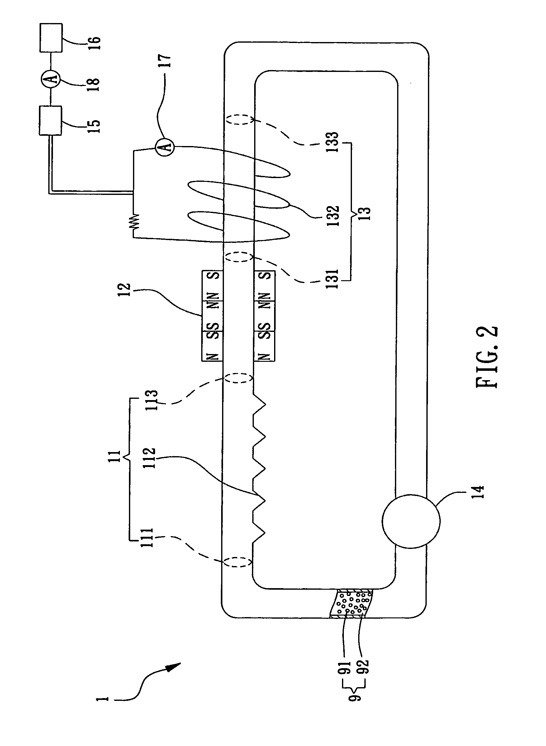
[0023]As described in Faraday's law, any change in the magnetic environment of a coil of wire will cause a voltage (emf) to be “induced” in the coil. No matter how the change is produced, the voltage causing an induced current will be generated. The change could be produced by changing the magnetic field strength, moving a magnet toward or away from the coil, moving the coil into or out of the magnetic field, rotating the coil relative to the magnet, etc.

[0024]It is noted that the induced current is proportional to the rate of change of the magnetic flux. That is, the size of the induced current can be made bigger by the means list as following: (1). Using a stronger magnet. (2). Moving the magnet at a faster speed. (3). Usin...


PUM


Abstract

A ferrofluid power generator with micro vortex generator is disclosed, which is capable of generating an induced current by enabling a ferrofluid having a plurality of magnetic particles to flow in a closed circuit, the device comprising a vortex generator and a induced current unit. The vortex generator further comprises a first inlet, a first outlet and a plurality of cavities, which is capable of accelerating the rotation speed of the magnetic particles by virtue of employing the plural cavities to enable the magnetic particles to rotate while the ferrofluid passing through the plural cavities. The induced current unit is substantially a tube having a second inlet and a second outlet, where the second inlet is coupled to the first outlet of the vortex generator for accepting the ferrofluid with rotating magnetic particles to flow therein and through so as to induce a change of magnetic flux to occur and generate an induced current accordingly.

Description

FIELD OF THE INVENTION[0001]The present invention relates to an electromagnetic power generator, and more particularly, to a ferrofluid power generator with micro vortex generator, in which the flowing of magnetic particles in a ferrofluid are accelerated by virtue of increasing the rotation of the same so as to enable the magnetic flux in a loop of wire to change according, where an induced current is generated.BACKGROUND OF THE INVENTION[0002]There are many types of electrical generators, most of which convert thermal energy to fluid energy to mechanical energy to electrical energy. The principal sources of electrical power convert thermal energy generated by burning coal or gas or by atomic fission to superheated steam which is then converted to rotary mechanical power through a turbine which, in turn, drives an electromechanical generator.[0003]It has also been proposed to use a closed loop ferrofluid system to drive a turbine for generation of power. In such a system, ferroflui...

Claims


Application Information

Patent Timeline
Patent Type & Authority Patents(United States)
IPC IPC(8): H02K44/00
CPCH02K44/08
Inventor HSU, LI-CHIEH
Owner IND TECH RES INST
Why Eureka
Try Eureka