Electrical generator having an oscillator containing a freely moving internal element to improve generator effectiveness

a generator and oscillator technology, applied in the direction of electric generator control, vessel auxillary drive, auxiliary drive, etc., can solve the problems of increasing the cost of operation of such devices, reducing the operational time and operation cost, and reducing the threshold for motion. , the effect of improving acceleration and performance capabilities

Inactive Publication Date: 2006-09-12
POWER ESTIMATE
View PDF53 Cites 117 Cited by
  • Summary
  • Abstract
  • Description
  • Claims
  • Application Information

AI Technical Summary

Benefits of technology

[0029]The present invention advantageously overcomes the drawbacks and disadvantages of previously known kinetic electrical power generators (hereinafter “KEPGs”) by providing a KEPG utilizing a novel oscillating weight with improved acceleration and performance capabilities resulting in a significantly lower motion threshold than any previously known KEPG, even when the oscillating weight is of relatively small size. In addition, the novel oscil

Problems solved by technology

Utilization of ordinary disposable batteries (alkaline, etc.) greatly increases the cost of operation of such devices, especially because many electrical devices (for example, digital cameras) draw electrical energy in such a way as to quickly exhaust a conventional battery.
In addition, users find frequent replacement of batteries and carrying spare batteries very inconvenient.
Nevertheless, while rechargeable batteries, especially the latest currently available models, offer longer operational time and lower cost of operation, they are still finite sources of electrical energy and must be recharged relatively often.
This is problematic for high utilization devices, such as PDAs, media recorders/players, portable telephones and laptop computers.
Furthermore, because recharging involves connecting the device or its battery to a land power line, the recharging process limits the user's mobility.
First, most batteries utilize non-recyclable toxic and/or environmentally polluting materials in their construction, making disposal of used batteries a environmental danger.
Second, all batteries generate heat during operation, requiring cooling in sensitive electronic equipment (such as in portable computers).
The heat generation from batteries is a particular danger in military devices where the heat signature exposes the carrier of the device to enemy infra-red or other heat sensing surveillance or targeting equipment.
However, this approach requires direct dedicated action by the user to generate the energy that

Method used


Image

  • Electrical generator having an oscillator containing a freely moving internal element to improve generator effectiveness
  • Electrical generator having an oscillator containing a freely moving internal element to improve generator effectiveness
  • Electrical generator having an oscillator containing a freely moving internal element to improve generator effectiveness

Examples


first embodiment

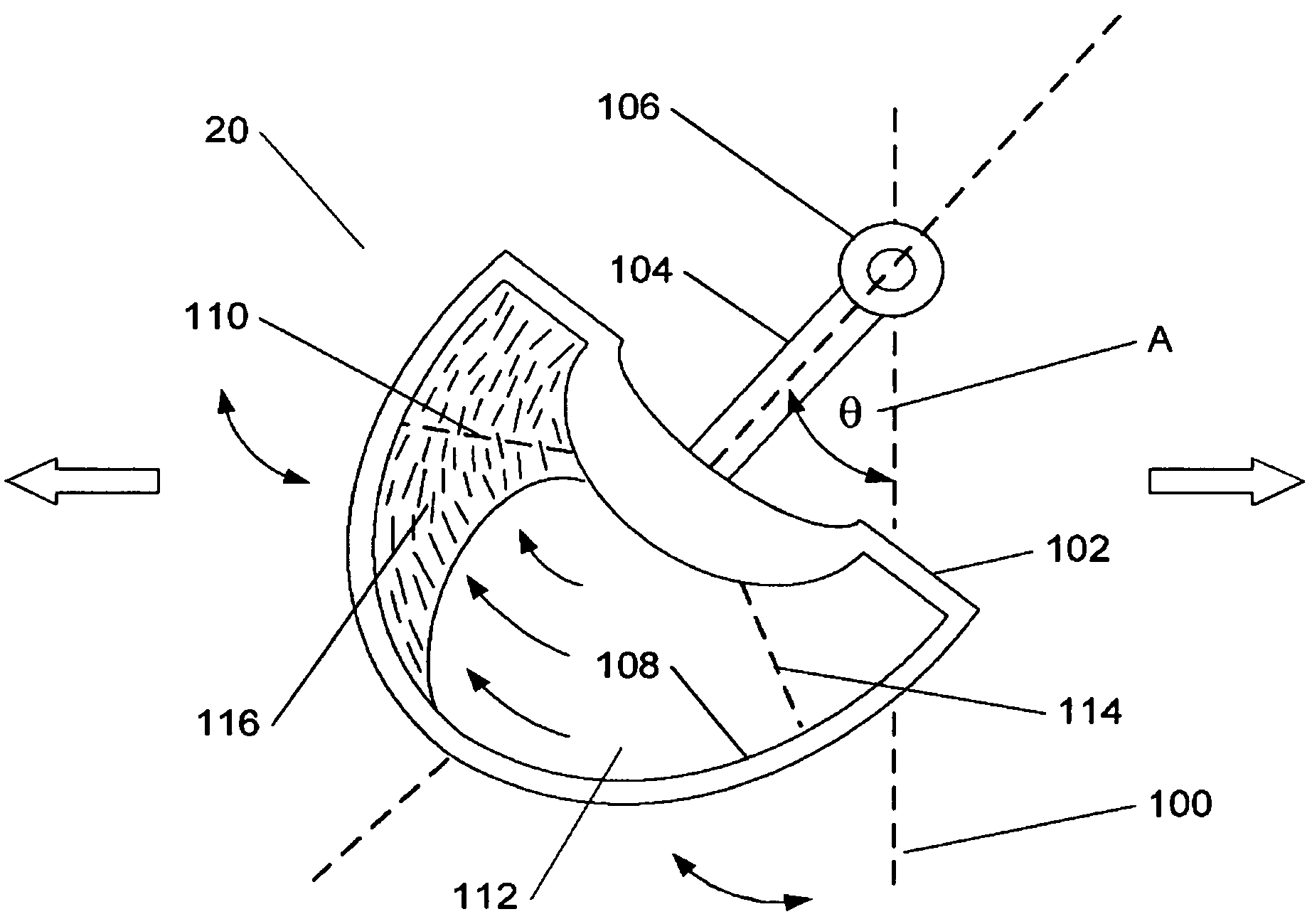
[0080]Referring now to FIGS. 4A and 4B, the oscillating weight 20 is shown. In FIG. 4A the oscillating weight 20 is shown in a stationary position, along an axis 100, when the oscillating weight 20 has not been subjected to a mechanical disturbance, while in FIG. 4B, the oscillating weight 20 is shown in an exemplary angularly displaced position when the oscillating weight has been subjected to a mechanical disturbance, along an axis 118 that is at an angle A with respect to the axis 100.

[0081]The oscillating weight 20 includes a weight body 102, a pivot coupling 106 for connection to the pivot element 22 (of FIG. 1), and an elongated connector 104 connected between the body 102 at one end, and the pivot coupling 106 at the other end. An internal cavity 108, positioned within the body 102, includes a first region 110, and a second region 114, corresponding to the first and second directions in which the weight 20 is capable of oscillating, and a central region 112, between the first...

second embodiment

[0084]Referring now to FIG. 5, the oscillating weight 20 is shown as an oscillating weight 150. The oscillating weight 150 includes a weight body 152, a pivot coupling 156 for connection to the pivot element 22 (of FIG. 1), and an elongated connector 154 connected between the body 152 at one end, and the pivot coupling 106 at the other end. An internal cavity 158, positioned within the body 152, includes a first region 160, and a second region 164, corresponding to the first and second directions in which the weight 150 is capable of oscillating, and a central region 162, between the first and second regions 160, 164, that is generally aligned with the longitudinal axis of the elongated connector 154. The oscillating weight 150, also includes an acceleration element 166, for example, one or more sliding elements composed of a dense substance (e.g. metal, glass, crystal, ceramic, or stone) or of a combination of two or more dense substances). The acceleration element 166 is preferabl...

third embodiment

[0085]Referring now to FIG. 6, the oscillating weight 20 is shown as an oscillating weight 200. The oscillating weight 200 includes a weight body 202, a pivot coupling 206 for connection to the pivot element 22 (of FIG. 1), and an elongated connector 204 connected between the body 202 at one end, and the pivot coupling 206 at the other end. An internal cavity 208, positioned within the body 202, includes a first region 210, and a second region 214, corresponding to the first and second directions in which (he weight 200 is capable of oscillating, and a central region 212, between the first and second regions 210, 214, that is generally aligned with the longitudinal axis of the elongated connector 204. The oscillating weight 200, also includes an acceleration element 216, for example, one or more rolling elements composed of a dense substance (e.g. metal, glass, crystal, ceramic, or stone) or of a combination of two or more dense substances). The rolling elements may be disks, sphere...


PUM


Abstract

An apparatus and method for providing electrical energy to an electrical device by deriving the electrical energy from motion of the device. In one embodiment, the inventive apparatus includes a novel kinetic electrical power generator (KEPG) consisting of an inventive oscillating weight having an internal cavity with a freely movable acceleration element disposed therein, resulting in improved acceleration and oscillation capabilities and lower motion threshold for the weight, a system for converting the weight's oscillating motion into rotational motion, and an electromechanical transducer system for generating electrical energy from the rotational motion. The novel KEPG includes components for modifying the electrical energy for storing and/or feeding the modified electrical energy to the electrical device. Optional components may be included for using the modified electrical energy to recharge one or more rechargeable batteries used in an electric device. Alternate advantageous embodiments of the inventive apparatus include, but are not limited to: a KEPG with multiple inventive oscillating weights to increase velocity and frequency of desirable rotational motion, and a KEPG system utilizing multiple electrically coupled KEPG sub-systems.

Description

CROSS REFERENCE TO RELATED APPLICATIONS[0001]The present patent application claims priority from the commonly assigned U.S. provisional patent application Ser. No. 60 / 468,917 entitled “Apparatus and Method for Generating Electrical Energy from Motion and From Routine Activities” filed May 8, 2003.FIELD OF THE INVENTION[0002]The present invention relates generally to an apparatus and method for generating electrical energy from motion, and more particularly to an apparatus and method for generating electrical energy from at least one kinetic electrical generator and processing the electrical energy to power electrical devices connected thereto, to recharge one or more rechargeable batteries, or to store the electrical energy for future use.BACKGROUND OF THE INVENTION[0003]The multitude of electrical and electronic devices in common use today, from cellular telephones to computers to lighting systems, all depend on a steady supply of electrical energy. Such a supply is not an issue wh...

Claims


Application Information

Patent Timeline
IPC IPC(8): F03B13/12E02B3/06E02B9/08F03B13/10H02P9/04B60L8/00B63J3/04F03B13/20H02K7/18
CPCB60L8/00B63J3/04F03B13/20H02K7/1892Y02T90/38Y02E10/38Y02T10/641Y02T10/7083Y02E10/30Y02T10/64Y02T10/7072Y02T90/40
Inventor BEDNYAK, VLADIMIR
Owner POWER ESTIMATE
Why Eureka
Try Eureka