Plasma display panel and driving method thereof

a technology of display panel and plasma, which is applied in the direction of static indicating devices, instruments, and address electrodes, etc., can solve the problems of deterioration in efficiency and brightness, deterioration of brightness, and extremely limited light-emission area within the discharge cell, and achieve high brightness and light-emission time. , the effect of high efficiency

Inactive Publication Date: 2006-09-12
LG ELECTRONICS INC
View PDF13 Cites 6 Cited by
  • Summary
  • Abstract
  • Description
  • Claims
  • Application Information

AI Technical Summary

Benefits of technology

[0013]Accordingly, it is an object of the present invention to provide a plasma display panel (PDP) wherein a discharge distance is increased to make a high efficiency, a light-emission area is enlarged to obtain a high brightness, and a light-emission time is increased to improve a light-emission efficiency.

Problems solved by technology

However, in such an AC-type PDP structure, since a distance between the scanning / sustaining electrode Ym and the common sustaining electrode Zm is short, a discharge path upon sustaining discharge is short to generate a small quantity of ultraviolet rays and a light-emission area within the discharge cell is extremely limited.
This causes a deterioration of brightness.
Also, the AC-type PDP structure has a problem in that, as a distance between the scanning / sustaining electrode Ym and the common sustaining electrode Zm is increased so as to increase the discharge path and the light-emission area, an erroneous discharge with other adjacent cells is generated.
Furthermore, a ratio of time contributing to a real light-emission in the entire sustaining interval during the sustaining period determining the brightness of the PDP is very low to cause a deterioration in the efficiency and the brightness.
As a result, since the major time of the sustaining interval SP is wasted for a formation of wall charges and a preparation for the next discharge, the entire sustaining interval fails to be exploited efficiently, thereby causing a deterioration in the discharge and light-emission efficiency and the brightness.

Method used


Image

  • Plasma display panel and driving method thereof
  • Plasma display panel and driving method thereof
  • Plasma display panel and driving method thereof

Examples


first embodiment

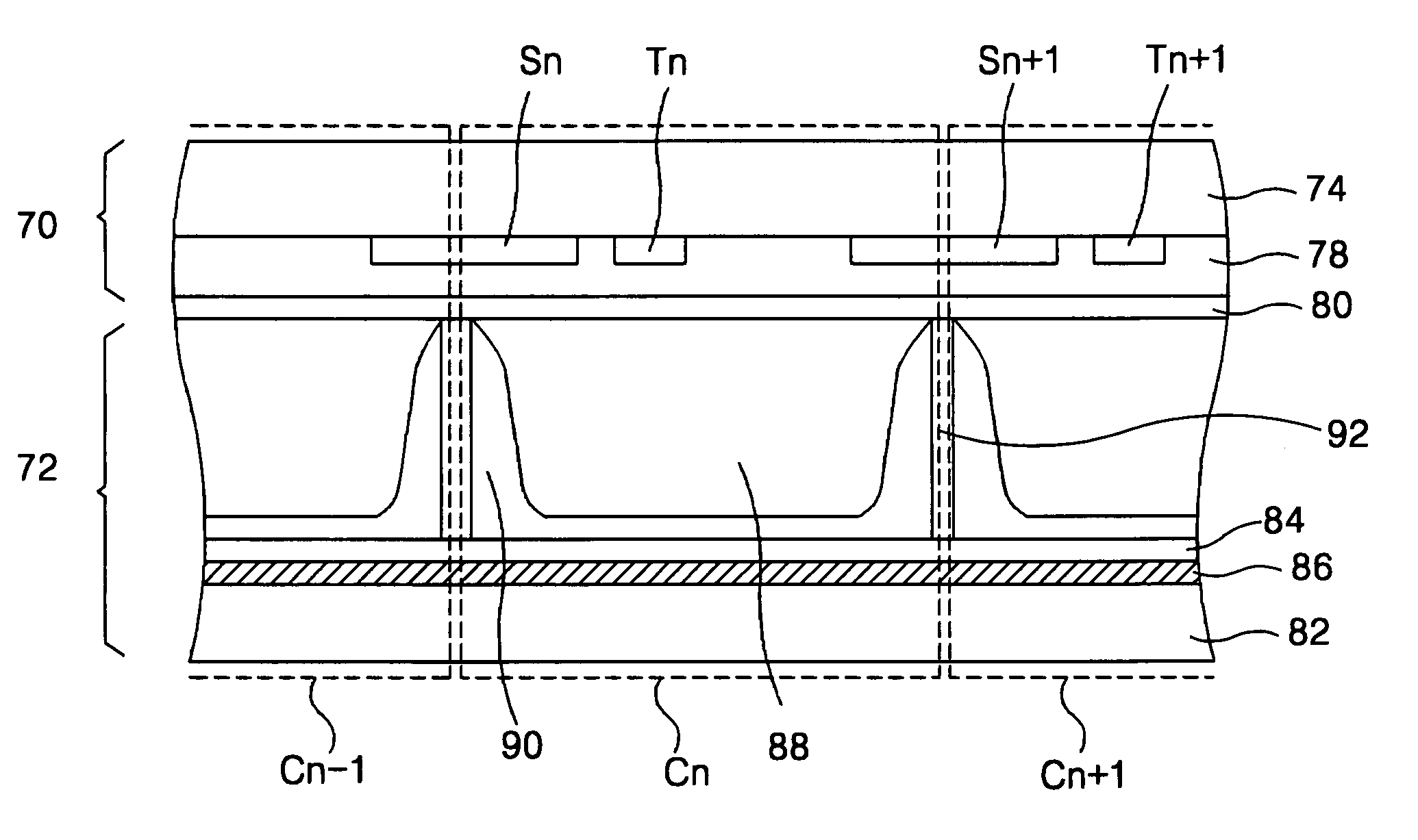
[0031]FIG. 5 is a vertical section view showing a discharge cell structure of an AC surface-discharge plasma display panel (PDP) according to the present invention. Referring to FIG. 5, the AC surface-discharge PDP includes a nth sustaining electrode Sn provided at the rear side of an upper glass substrate 74 at a boundary portion between a (n−1)th discharge cell Cn−1 and a nth discharge cell Cn, and a nth trigger electrode Tn provided at the rear side of the upper glass substrate 74 in such a manner to be spaced at a small distance from the nth sustaining electrode Sn at the nth discharge cell Cn in order to cause a primary sustaining discharge along with the nth sustaining electrode Sn.

[0032]As shown in FIG. 5, the nth trigger electrode Tn is arranged between the nth sustaining electrode Sn and a (n+1)th sustaining electrode Sn+1, and a distance between the nth trigger electrode Tn and the (n+1)th sustaining electrode Sn+1 is set to be larger than that between the nth sustaining e...

second embodiment

[0039]FIG. 8 shows a discharge cell structure of a AC surface-discharge PDP according to the present invention.

[0040]The second embodiment has a difference from the first embodiment in that a metal bus electrode 76 having a light-shielding property is formed at each center of the rear sides of sustaining electrodes Sn and Sn+1 and trigger electrodes Tn and Tn+1. Other elements and features in the second embodiment are identical to those in the first embodiment.

[0041]A driving method for the second embodiment of the present invention is identical to that for the first embodiment shown in FIG. 1. In the sustaining interval SP after an address discharge, a primary priming discharge is generated between the nth sustaining electrode Sn and the nth trigger electrode Tn having a narrow distance from each other at the nth discharge cell Cn. Subsequently, a secondary sustaining discharge having a long discharge path is generated between the (n+1)th sustaining electrode Sn+1 and the nth trigg...

third embodiment

[0042]FIG. 9 shows a structure of an AC surface-discharge PDP according to the present invention.

[0043]When the third embodiment shown in FIG. 9 is compared with the first embodiment shown in FIG. 6, it has a structure in which any horizontal barrier ribs does not exist between the scanning lines. As mentioned above, a sustaining discharge at the nth discharge cell Cn is caused by three electrodes of the nth sustaining electrode Sn, the nth trigger electrode Tn and the (n+1)th sustaining electrode Sn+1 to achieve a high efficiency and a high brightness. Since the third embodiment has barrier ribs taking a stripe shape rather than a lattice shape, it has an advantage in that a panel structure and a manufacturing process can be simplified. However, the PDP according to the third embodiment does not have any horizontal barrier ribs for dividing the sustaining electrode lines S1, S2, S3, S4, . . . , but has only vertical barrier ribs 92 formed in a direction parallel to the address elec...


PUM


Abstract

A plasma display panel and a driving method thereof that are capable of improving the discharge efficiency and the brightness. In the panel, sustaining electrodes are formed at the boundary portions between the discharge cells. Trigger electrodes are formed at the inner sides of the discharge cells. Lattice-shaped barrier ribs are formed in such a manner to surround the discharge cells. The method of driving the panel includes a reset period, an address period and a sustaining period. In the method, a reset pulse is applied to the sustaining electrodes during the reset period. A scanning pulse is applied to the trigger electrodes during the address period. A first sustaining pulse is applied to the trigger electrodes during the sustaining period. A second sustaining pulse is applied to the sustaining electrodes in such a manner to be alternate with the first sustaining pulse. Accordingly, the PDP causes a sustaining discharge using three electrodes within the discharge cell to increase a discharge frequency per sustaining pulse into two time in comparison to the prior art and to make a long-distance discharge and an enlargement of light-emission area, thereby realizing a high efficiency and a high brightness.

Description

BACKGROUND OF THE INVENTION[0001]1. Field of the Invention[0002]This invention relates to a plasma display panel, and more particularly to a plasma display panel that is capable of improving the discharge efficiency and the brightness. The present invention also is directed to a method for driving the plasma display panel.[0003]2. Description of the Related Art[0004]Generally, a plasma display panel (PDP) radiates a fluorescent body by an ultraviolet with a wavelength of 147 nm generated during a discharge of He+Xe or Ne+Xe gas to thereby display a picture. Such a PDP is easy to be made into a thin-film and large-dimension type. Moreover, the PDP provides a very improved picture quality owing to a recent technical development. Such a PDP is largely classified into a direct current (DC) type and an alternating current (AC) type. The DC-type PDP causes an opposite discharge between an anode and a cathode provided at a front substrate and a rear substrate, respectively to display a pic...

Claims


Application Information

Patent Timeline
Patent Type & Authority Patents(United States)
IPC IPC(8): G09G3/28G09G3/20G09G3/288G09G3/291G09G3/293G09G3/294G09G3/298H01J11/12H01J11/14H01J11/22H01J11/24H01J11/26H01J11/28H01J11/32H01J11/34H01J11/36
CPCG09G3/293H01J11/12G09G3/2983G09G3/2942G09G3/294
Inventor KIM, JAE SUNGLEE, EUN CHEOLKANG, SEOK DONG
Owner LG ELECTRONICS INC
Why Eureka
Try Eureka