
Road white line recognition apparatus and method

a recognition apparatus and white line technology, applied in the direction of instruments, ways, images, etc., can solve problems such as the whole system's operation stop, and achieve the effect of reducing the performance deterioration of detecting and high accuracy

Inactive Publication Date: 2006-09-12
NISSAN MOTOR CO LTD
View PDF13 Cites 18 Cited by
  • Summary
  • Abstract
  • Description
  • Claims
  • Application Information

AI Technical Summary

Benefits of technology

[0007]In a case where the contrast of a road image is varied, the luminance threshold value is dynamically corrected. Hence, it is possible to reduce a performance deterioration of detecting the white line against a contrast variation between the white line and road surface developed in a case where the vehicle has entered such a road surface that a paint state of the white line becomes thin due to a wear of the road white line caused by repetitive vehicular tires' run on the road surface and against a contrast variation between the white line and paved road surface developed when a quantity of light inputted to the photographing means is reduced due to a change in a weather from a fine weather to a cloudy weather. That is to say, the luminance value (gray level value) of the whole photographed image of an ordinary road surface during the fine weather or cloudy weather is substantially uniform and only an optical density of pixels (luminance) on the white line corresponding portion of the image indicates a prominent value. Hence, since a clear difference in the gray level of pixels (luminance) occurs between the white line corresponding portion and any portion other than the white line, the white line can be detected with high accuracy.
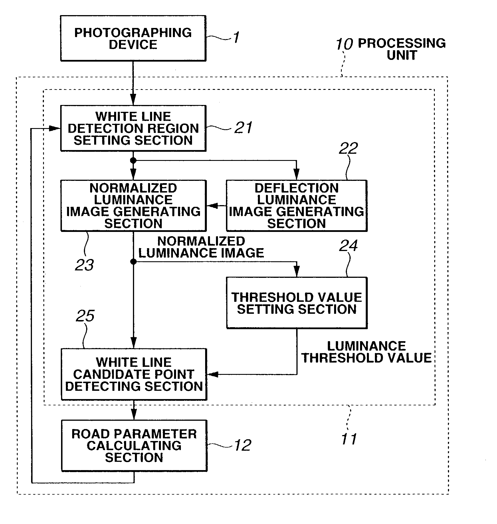
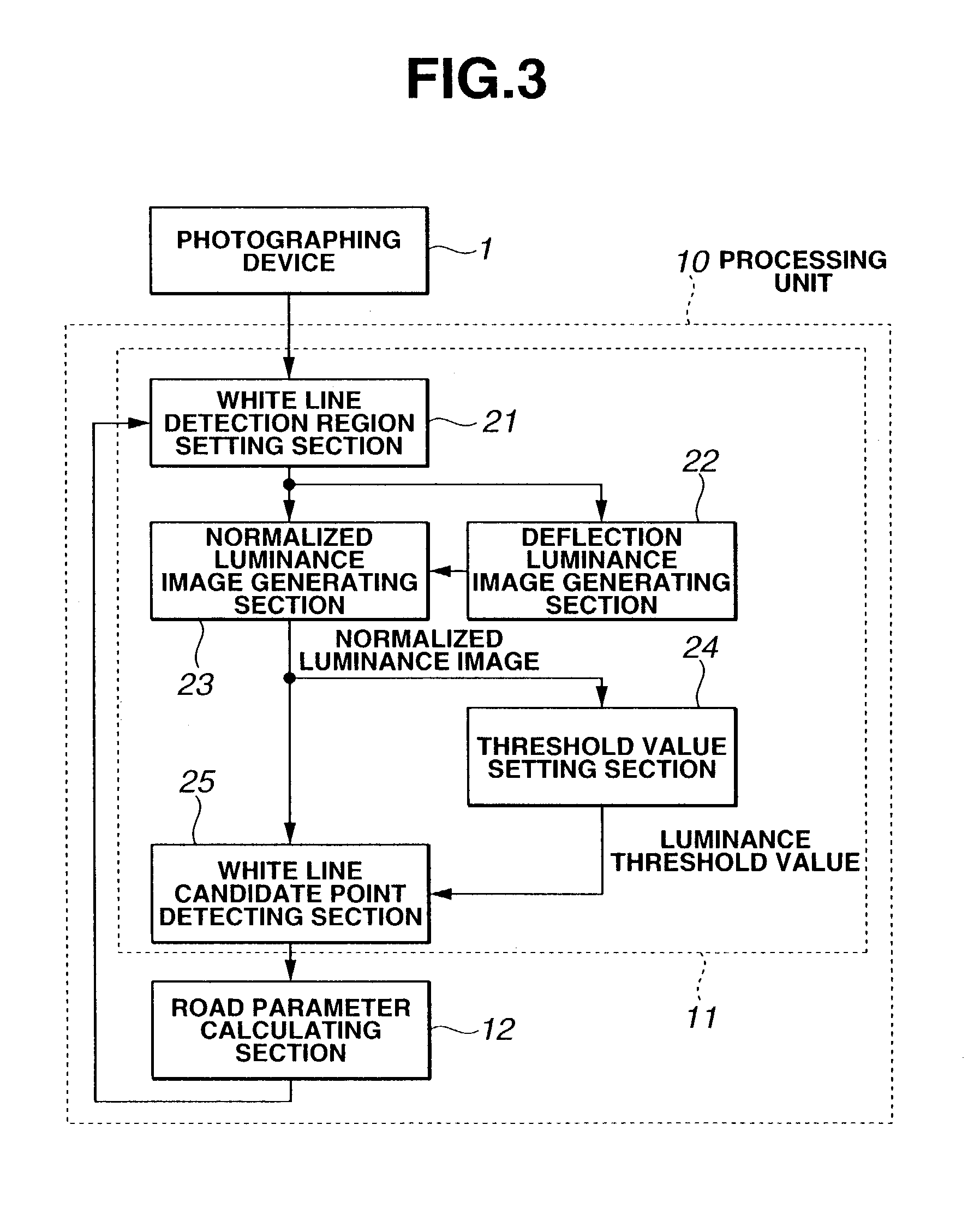
[0008]However, especially during a rainy weather, as a vehicle body becomes approached to a front center or as a distance from the photographing means to a photographed object, viz., to a white line segment becomes long, a reflected light due to a water film becomes intense (the quantity of light becomes increased). Hence, a deflection of the luminance over the photographed image within the threshold value calculating region to calculate the luminance (gray level) threshold value used to extract the white line from the region cannot be neglected. The luminance of the image portion having the film of water is often approximately equal to or higher than that of the white line. Therefore,it is difficult to set an appropriate threshold value of the luminance since a maximum value of the luminance within the threshold value calculating region corresponds to that of a portion having the film of water or an average gray level within the threshold value calculating region becomes approached to the luminance value of the white line or maximum luminance value thereof. Such a phenomenon as described above occurs not only during the rainy weather but also during a vehicular run at an exit of a tunnel or in a tunnel. That is to say, such a phenomenon as described above is easy to occur in such cases where light beams enter directly the photographing means from each light source as governed by an optical phenomenon and there is a road surface on which the light beams are easy to be reflected or as a plurality of light sources are present.
[0010]It is, hence, an object of the present invention to provide road white line recognition apparatus and method which are capable of detecting accurately the road white line irrespective of a spatial deflection of the luminance.

Problems solved by technology

An erroneous detection of the white line brings an operation stop of the whole system.

Method used


Image

  • Road white line recognition apparatus and method
  • Road white line recognition apparatus and method
  • Road white line recognition apparatus and method

Examples


Embodiment Construction

[0029]Reference will hereinafter be made to the drawings in order to facilitate a better understanding of the present invention.

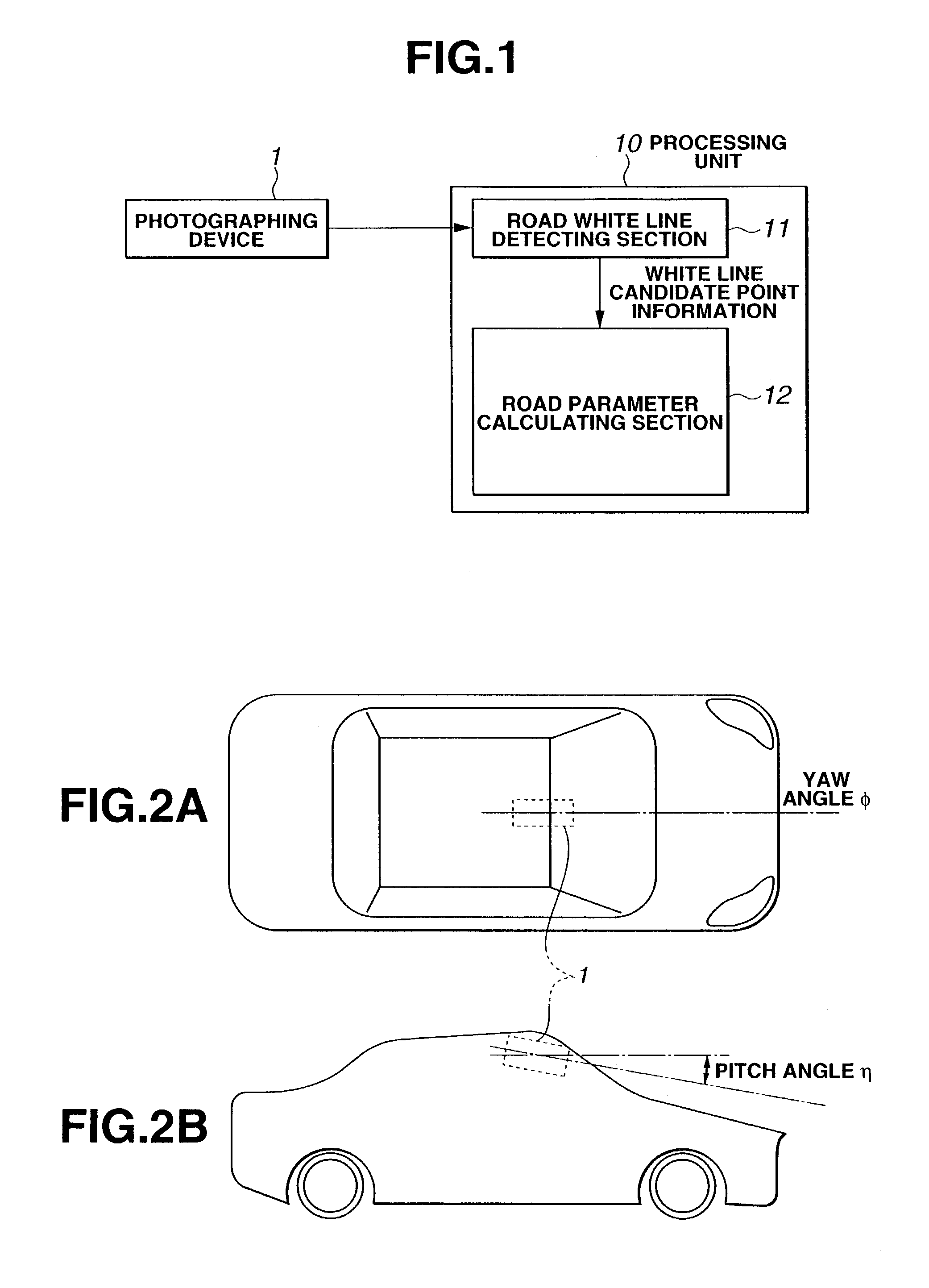
[0030]FIG. 1 shows a configuration view representing a preferred embodiment of a road white line recognition apparatus according to the present invention. In FIG. 1, a photographing device 1 constituted by a CCD (Charge Coupled Device) camera or so forth is mounted, for example, as shown in FIGS. 2A and 2B, on an upper middle part of a front windshield of a vehicle body within a vehicle compartment which is located at a center in a vehicular width direction. Then, a, so-called, a yaw angle φ between an optical axis of a lens of photographing device 1 and a vehicular center line is set to zero and a, so-called, pitch angle η is αrad. A vehicular surrounding environment including a road segment located on a front area of the vehicle is photographed. The photograph information photographed by above-described photographing deice 1 is inputted into a processing ...


PUM


Abstract

In road white line recognition apparatus and method, a road extended in a forward direction of a vehicle is photographed through a photographing device, a deflection luminance information when a luminance information of an image photographed by the photographing device is represented by a luminance information that a surface of the road naturally has and the deflection luminance information from which the luminance information that the road surface naturally has is excluded is detected on the basis of an approximation function obtained by approximating the luminance information of the photographed image to a horizontal direction of the photographed image, a normalized luminance information is detected by removing the deflection luminance information from the luminance information of the photographed image, and a road white line is detected on the basis of the normalized luminance information.

Description

BACKGROUND OF THE INVENTION[0001]1. Field of the Invention[0002]The present invention relates to road white line recognition apparatus and method to recognize a road white line used for displaying a traffic lane divisional zone on a road surface on which the vehicle travels.[0003]2. Description of the Related Art[0004]Various techniques for recognizing a road white line (or road white lines) through a monitor image and a relationship between the vehicle and the road white line is used for a vehicular automatic control or partially for an automatic control (for example, a vehicular velocity control system or a vehicular lane keep control system) have conventionally been proposed.[0005]A Japanese Patent Application First Publication No. Heisei 5-347000published on Dec. 27, 1993 discloses a previously proposed road white line recognition apparatus. In the disclosed road white line recognition apparatus, white line candidate points constituting each road white line are detected from the...

Claims


Application Information

Patent Timeline
IPC IPC(8): G06K9/00G01B11/24B60R21/00G06T1/00G06T3/00G06T5/00G06T7/60G06V10/40G08G1/16
CPCG06K9/00798G06K9/46G06T7/0081G06T2207/30256G06T2207/10016G06T7/11G06V20/588G06V10/40
Inventor SHIMAKAGE, MASAYASU
Owner NISSAN MOTOR CO LTD
Learn More