Transmitter and a modulator therefor

a technology of modulator and transmitter, which is applied in the direction of transmission, antenna, amplification control details, etc., can solve the problems of generating 90 phase shift, inherently limited to substantially narrow band applications, and difficult to integrate such networks onto an ic, and achieve high local oscillation

Inactive Publication Date: 2006-09-12
NOKIA MOBILE PHONES LTD
View PDF41 Cites 7 Cited by
  • Summary
  • Abstract
  • Description
  • Claims
  • Application Information

AI Technical Summary

Benefits of technology

[0010]The local oscillator can be fixed to operate at a sub-harmonic of the transmitted signal frequency, and the mixing action is performed between the baseband signal and one of the harmonics of the local oscillator, which advantageously ensures that the harmonic is not generated in the transmitter. This is termed sub-harmonic mixing. Accordingly, the local oscillator signal frequency is far removed from transmitted signal frequency, resulting in the mixer providing very high local oscillation to transmitted signal isolation.
[0011]A further advantage is that the high local oscillator isolation allows the output level of the modulator to be controlled over a large range before local oscillator breakthrough becomes a problem.

Problems solved by technology

Therefore, one of the issues with direct conversion transmitter design is that of generating the 90 phase shift for the ‘Q’ LO signal.
The passive phase shift network approach involves the design of a frequency selective ‘All Pass’ filter network to provide the phase difference between the ‘I’ and ‘Q’ local oscillators but has the disadvantage that it is inherently limited to substantially narrow band applications and also that it can be difficult to integrate such networks onto an IC.
The active divide-by-two circuit has the disadvantage that it requires high current to operate and requires an LO of double the frequency of operation.
A separate issue, but one that is also important in the design of a direct conversion transmitter, is that of the gain control of the transmitter.
Thus, since the LO is operating at the wanted radio frequency, problems of LO leakage and shielding can become very significant.
These approaches however have not satisfactorily provided the wide range of power control required.
A further concern with direct conversion transmitters is that the LO signal cannot be provided directly from a synthesiser locked VCO.
Firstly, if the radiotelephone has an internal antenna there is a very great risk that the transmitter will radiate back into the synthesiser locked VCO and cause it to go out of lock or generate spurious signals.
Secondly, there will be insufficient isolation between antenna impedance (which will vary a great deal as the user moves around) and the synthesiser locked VCO.
This will cause the synthesiser locked VCO to either go out of lock or generate spurious signals.
This however, increases component count and current consumption.

Method used


Image

  • Transmitter and a modulator therefor
  • Transmitter and a modulator therefor
  • Transmitter and a modulator therefor

Examples


Embodiment Construction

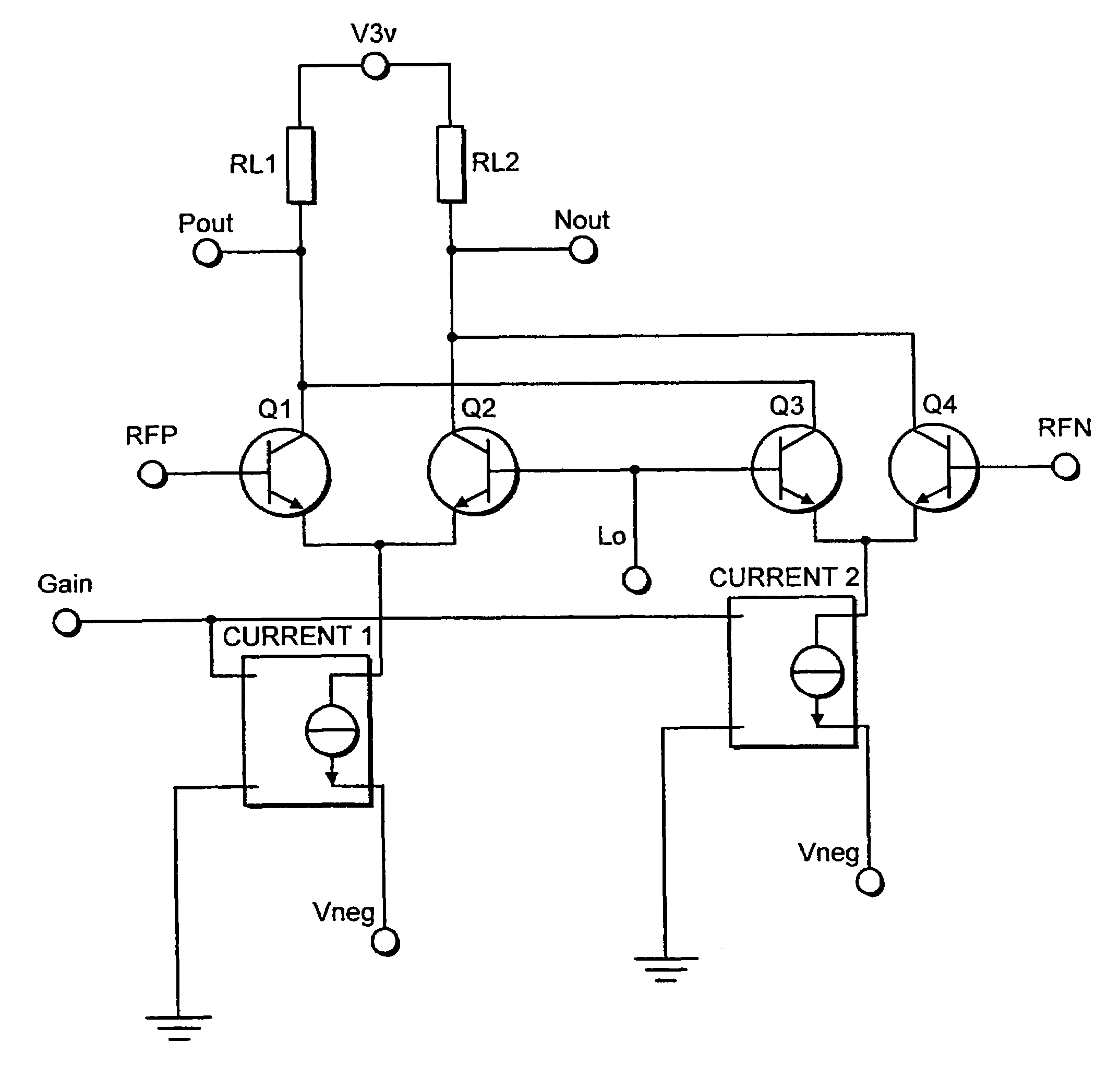
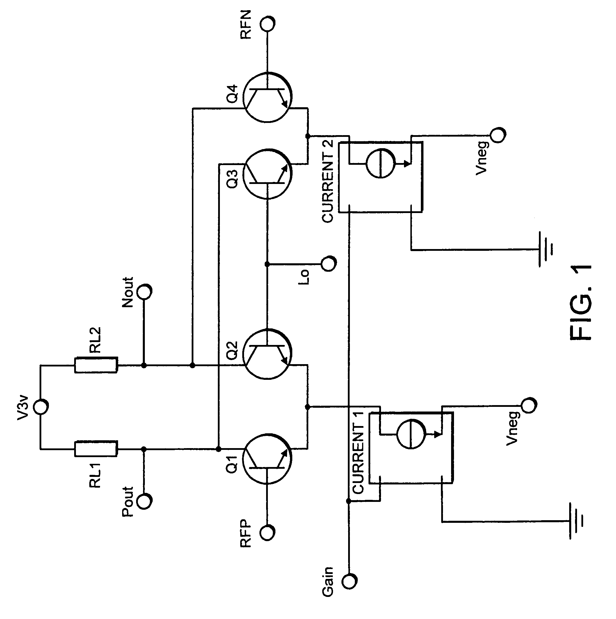
[0024]Referring initially to FIG. 1 there is shown an exemplary modulator circuit diagram of the present invention. In this circuit a suitable power supply is connected at V3v ie. 3 volts. The power supply V3v is connected to the output loads of the modulator circuit, the load being represented by resistors RL1 and RL2. These however may be reactive, resistive or active whichever is most suitable in the application. The output loads RL1 and RL2 are connected respectively to Pout and Nout which are the differential outputs of the modulator circuit. The signal present between Pout and Nout is the modulated radio frequency carrier. In the case of an ‘I / Q’ modulator this differential output would be summed with the differential output of a second modulator. The summed output would then be passed to the next stage of the transmitter.

[0025]Pout and Nout are coupled to the transistor network forming the switching means of the modulator circuit. The transistors Q1,2,3,4 are shown as bipolar...


PUM


Abstract

A transmitter for a portable radio communication apparatus comprising a modulator having first port for inputting a baseband signal and a second port for inputting a local oscillator signal, and including means for rectifying the input local oscillator signal to provide a conductance waveform at a multiple of the local oscillator signal, and means for mixing the baseband signal with the conductance waveform at said multiple of the local oscillator signal frequency for up-converting the baseband signal to a radio frequency modulated carrier, the transmitter including means for controlling the gain of the modulator thereby to control the output level of the modulator.

Description

BACKGROUND OF THE INVENTION[0001]The present invention relates to a transmitter for a portable radio communication apparatus, and more particularly to a modulator for a direct conversion transmitter.[0002]A general trend in portable communication apparatus is the reduction in volume, weight and power consumption of such apparatus. This has led to efforts towards reducing the number of elements and devices necessary to perform the functions associated with portable communication devices. In particular, the radio frequency transmit strip of portable communication apparatus, which typically comprises a number of up-converting stages, is an area in which a reduction in the number of elements and devices would be beneficial.[0003]One approach to reduce the number of stages in the radio frequency transmit strip is to convert a baseband signal (comprising the information to be transmitted) to a radio frequency carrier signal in a single step. This is termed direct conversion or direct modu...

Claims


Application Information

Patent Timeline
Patent Type & Authority Patents(United States)
IPC IPC(8): H04B1/06H03C1/36H03G1/00
CPCH03G1/0023H03C1/36
Inventor FURMIDGE, SIMON
Owner NOKIA MOBILE PHONES LTD
Why Eureka
Try Eureka