Cartridge munition, particularly one of medium caliber

a medium-caliber, cartridge-type technology, applied in the field of cartridge-type ammunition, can solve the problems of significant damage, reach and exceed 220° c., storage or transportation system, and impede the separation of the cartridge shell

Active Publication Date: 2006-09-19
NICO PYROTECHNIK HANNS JUERGEN DIEDRICHS GMBH & CO KG
View PDF16 Cites 18 Cited by
  • Summary
  • Abstract
  • Description
  • Claims
  • Application Information

AI Technical Summary

Benefits of technology

[0011]It is the object of the invention to present measures intended to prevent separation of the cartridge shell from the projectile when there is a sharp increase in ambient temperature above the ignition temperature of the pyrotechnic igniter charge.
[0012]Another object of the invention is to present measures intended to prevent damage to the environment caused by a collection of many such cartridges, e.g., in a storage or transport container, upon sharp increase in ambient temperature such as caused by a fire.
[0013]Another object of the invention is to weaken the effect of the main charge after ignition of the igniter charge so that neither large pressure damage nor major mechanical damage results.

Problems solved by technology

However, a fire in the storage or transport system during which temperatures reach and exceed 220° C. presents a risk.
Significant damage may result simply from the quantity of exploded propulsive charges of a large number of cartridges.
However, the cartridge shell and projectile may cause great damage while flying apart.
Any receiver containers involved will be destroyed, whereby the separated cartridge shells and projectiles may endanger humans and cause major mechanical damage.
The cartridge shell and projectile were blown apart and thrown up to 100 meters as a result of the pressure buildup in the propulsion chamber, so that the energy released when many such cartridges catch fire is considerable.

Method used


Image

  • Cartridge munition, particularly one of medium caliber
  • Cartridge munition, particularly one of medium caliber

Examples


Embodiment Construction

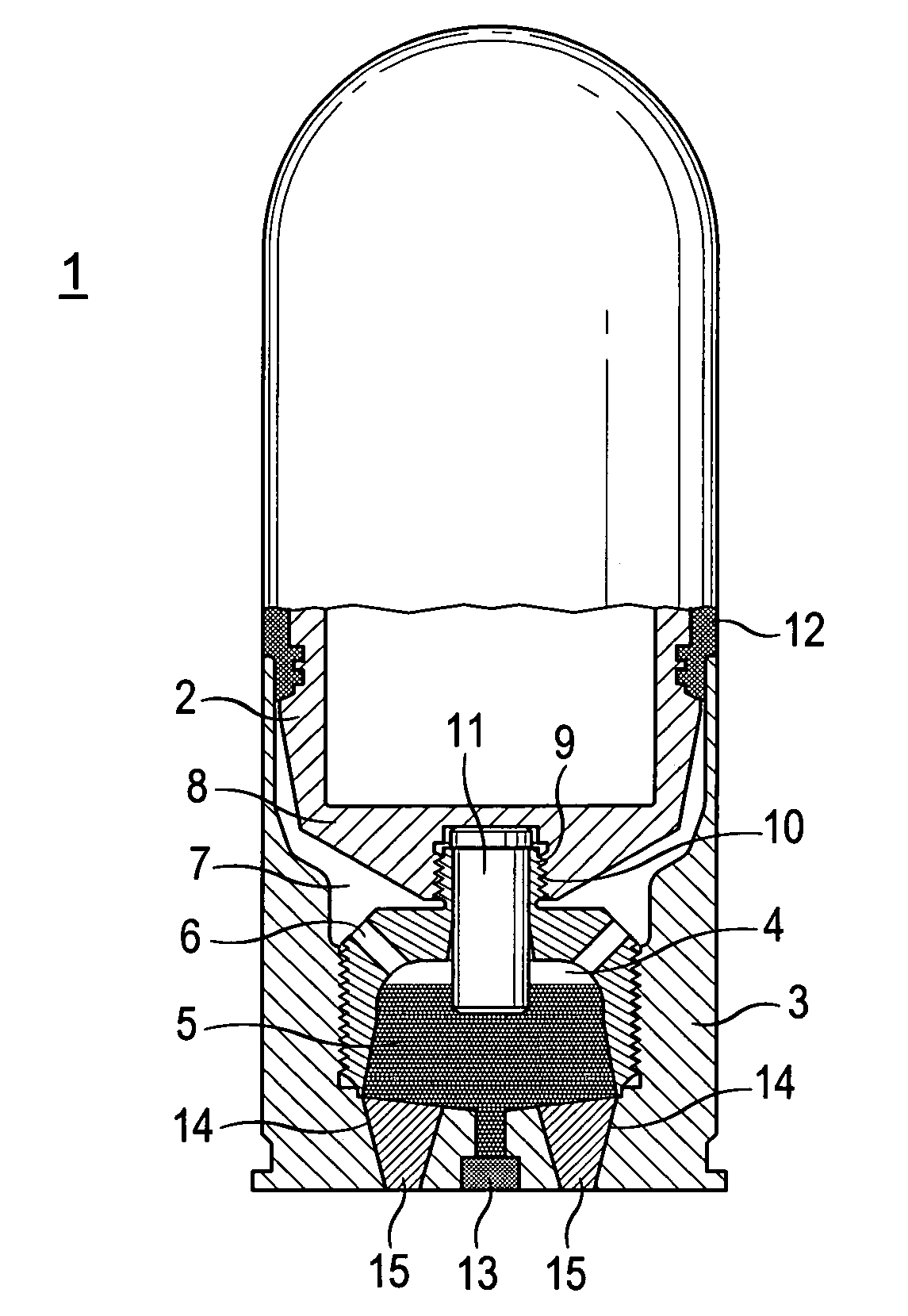
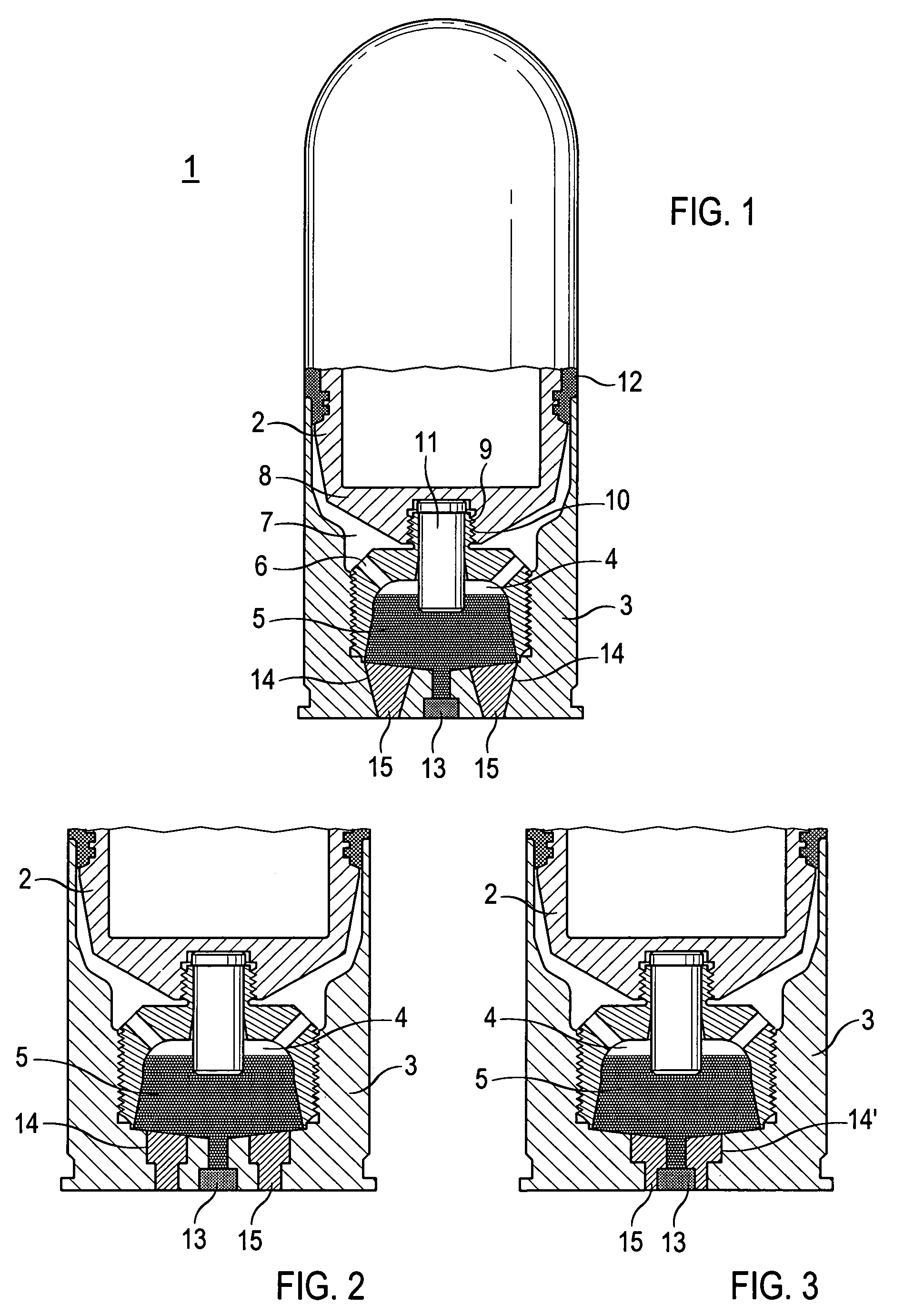
[0025]The preferred embodiments of the present invention will now be described with reference to FIGS. 1–3 of the drawings. Identical elements in the various figures are designated with the same reference numerals.

[0026]A cartridge munition 1 shown in FIG. 1 consists of a projectile 2 and a cartridge shell 3. The cartridge shell 3 includes a propulsion chamber 4 in which a propulsive charge 5 is positioned.

[0027]The wall of the propulsion chamber 4 is provided with overflow openings 6 that feed into a low-pressure chamber 7 positioned below the projectile base 8. The propulsion chamber 4 is provided with a central threaded stud 9 that engages in an inner thread in the projectile base. In addition, a tracer composition 11 is connected with the projectile base 8 that extends through the threaded stud 9 into the propulsion chamber.

[0028]The cartridge 1 possesses a caliber of from 40 mm, for example, and is fired from a tube weapon (not shown) with a twist, for which purpose the project...


PUM


Abstract

A cartridge munition, particularly practice round, includes a cartridge shell (3) and a projectile (2) inserted into it. A propulsion chamber (4) is provided within the cartridge shell that receives a propulsive charge (5) that may be ignited by means of a pyrotechnic igniter (13) and that develops propulsive gases that act on the base (8) of the projectile, driving it out of the cartridge shell. In order to prevent the pyrotechnic igniter from igniting spontaneously, and from igniting the propulsive charge (5) because of the ambient temperature or because of a fire, which would cause the cartridge shell and projectile to be separated and fly apart, it is proposed by the invention to provide exhaust channels (14) between the propulsion chamber and the exterior of the cartridge shell (3) that are filled with a fusible material, particularly a fusible metal (15). The fusible material has a lower melting point than the ignition point of the igniter (13) and of the propulsive charge (5). If the ambient temperature of the cartridge shell rises above the melting point of the fusible material, it melts, releasing the exhaust channels (14), so that, upon delayed ignition of the propulsive charge, it burns without pressure buildup, and the cartridge shell and projectile remain together.

Description

BACKGROUND OF THE INVENTION[0001]The invention relates to a cartridge munition, particularly to one of medium caliber, and here particularly to a practice round, with a cartridge shell and a projectile inserted into it, and with the cartridge shell mechanically attached to the projectile. A propulsion chamber is provided at the base of the cartridge shell to receive a propulsive charge that, for example, may be ignited using an igniter cap. After ignition, the propulsive gases from the propulsive charge act on the base of the projectile so that, after release of the mechanical bond between cartridge shell and projectile, the projectile is driven out of the cartridge shell.[0002]Such a cartridge munition is described in the U.S. Pat. No. 5,936,189. This cartridge munition is used with rapid-fire weapons of medium caliber (about 40 mm). Many such cartridges are received into a belt that is fed to the rapid-fire weapon. The propulsion chamber in the cartridge shell is sub-divided into ...

Claims


Application Information

Patent Timeline
Patent Type & Authority Patents(United States)
IPC IPC(8): F42B39/20F42B5/28F42B5/02F42B8/02
CPCF42B8/02F42B39/20
Inventor HAESELICH, DETLEF
Owner NICO PYROTECHNIK HANNS JUERGEN DIEDRICHS GMBH & CO KG
Why Eureka
Try Eureka