Weathervaning LNG offloading system

a technology of weathervane and offloading system, which is applied in the direction of special purpose vessels, container discharging methods, vessel construction, etc., can solve the problem of relatively unstable offloading situation during weathervan

Inactive Publication Date: 2006-09-19
SINGLE BUOY MOORINGS INC
View PDF9 Cites 20 Cited by
  • Summary
  • Abstract
  • Description
  • Claims
  • Application Information

AI Technical Summary

Benefits of technology

[0021]In again another embodiment, the regasification plant is placed on a tower above water level, the transverse section of the mooring arm being attached to a buoy that is connected to the tower via a soft yoke construction or via a rotatable hinging construction. For offloading of LNG to the regasification plant, a tra

Problems solved by technology

Even though the combined tanker and LNG regasification barge can weathervane around th

Method used


Image

  • Weathervaning LNG offloading system
  • Weathervaning LNG offloading system
  • Weathervaning LNG offloading system

Examples


Embodiment Construction

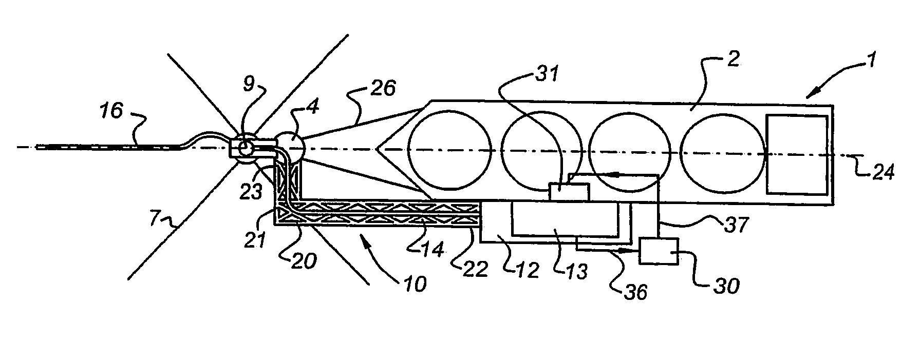
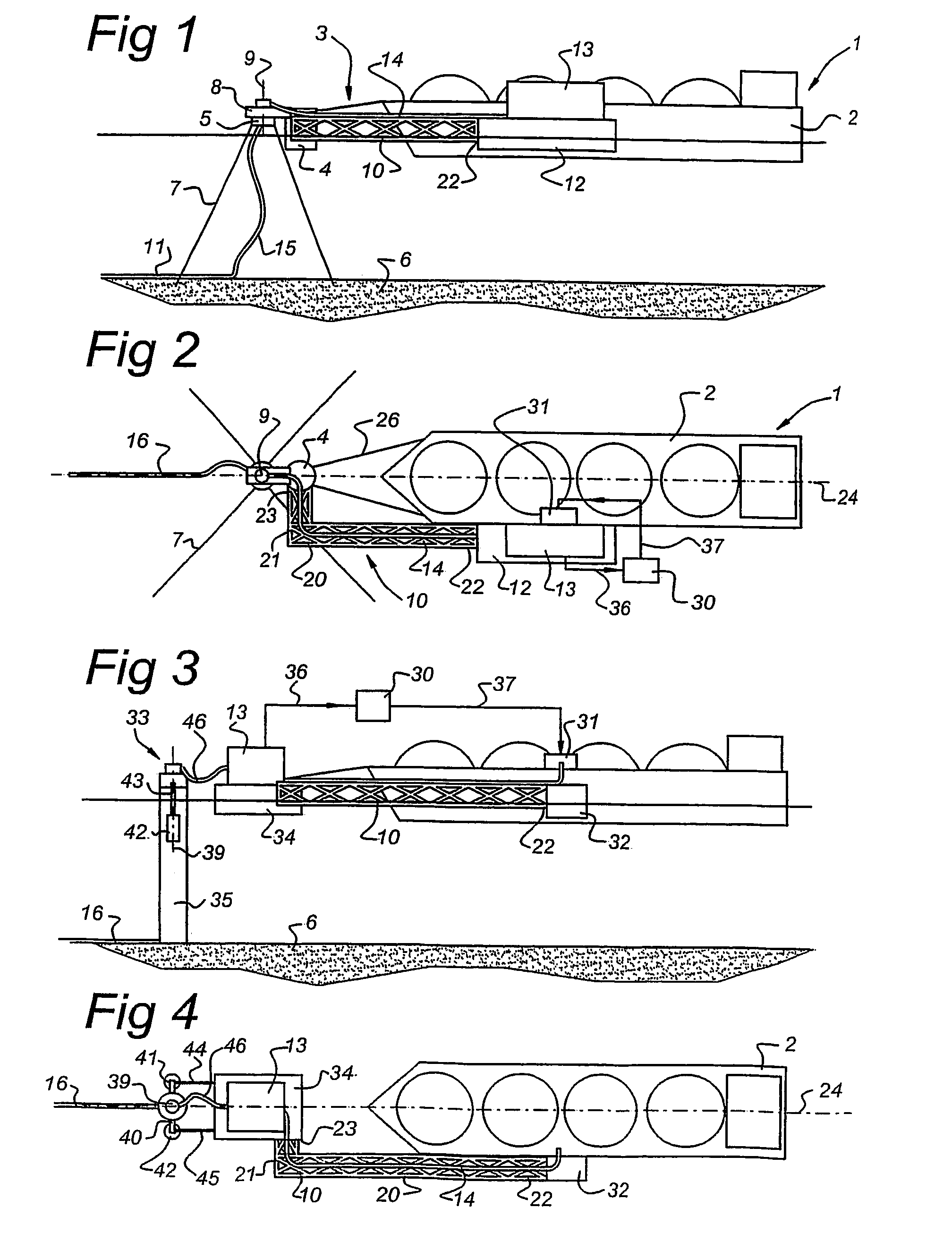
[0032]FIG. 1 shows the cryogenic offloading system 1 according to the present invention. The system comprises an LNG-tanker 2 and an offshore mooring structure 3. The offshore mooring structure 3 comprises a buoy 4 attached to a chain table 5. The chain table 5 is anchored to the seabed 6 via anchor chains or mooring lines 7. The upper part 8 of the buoy 4 can rotate relative to the stationary part 5 around vertical axis 9. The buoy 4 is connected to the vessel 2 via a connecting member, or space frame 10 extending alongside the tanker 2. The frame 10 is attached with a first end 22 to a floating structure 12 on which a processing unit 13 is placed. The processing unit 13 is in the embodiments described herein a regasification plant, but can comprise other equipment for LNG processing, such as an LNG pressurisation station and a vapour liquefaction installation.

[0033]The floating structure 12 is moored alongside the tanker 2 as can be clearly seen in FIG. 2. The regasification plant...


PUM


Abstract

A cryogenic fluid offloading system, having a tanker vessel (2) moored in line with an offshore mooring construction (4, 8) and connected to a processing unit, such as regasification plant (13). The degasification plant (13) has no large storage facilities, the tanker (2) being unloaded in dependence on onshore demand for gas.

Description

BACKGROUND OF THE INVENTION[0001]The invention relates to a cryogenic fluid offloading system comprising:[0002]an offshore mooring structure, connected to the seabed,[0003]a connecting member that is attached to the mooring structure with a first end to be displaceable around a vertical axis,[0004]a tanker vessel for loading cryogenic fluid at a first location, transporting it and offloading the cryogenic fluid at a second location, the tanker vessel being connected to the mooring structure via the connecting member,[0005]a first fluid duct connected to the mooring structure, for supplying fluid away from the mooring structure,[0006]a second fluid duct connected to the mooring structure, for transporting fluid coming from the tanker vessel to the mooring structure,[0007]a processing unit for receiving a cryogenic fluid in liquid phase from the tanker vessel and for supplying a gaseous phase of the fluid to the first fluid duct, and[0008]fluid supply means for controlling supply of c...

Claims


Application Information

Patent Timeline
IPC IPC(8): B63B3/24B63B22/02B67C3/34B63B27/24E02B3/20F17C9/02
CPCB63B22/026B63B27/34E02B3/20F17C9/02B63B27/24F17C2270/0126F17C2221/033F17C2223/0161F17C2223/033F17C2223/046F17C2225/0123F17C2225/035F17C2250/032F17C2250/0443F17C2265/05F17C2270/0105F17C2270/0123
Inventor WILLE, HEINQUEAU, JEAN-PIERREPOLDERVAART, LEENDERT
Owner SINGLE BUOY MOORINGS INC
Why Eureka
Try Eureka