System and method for generating power

a technology of electrical power generation and system, applied in the direction of electric generator control, emergency power supply arrangement, hybrid vehicles, etc., can solve the problems of increasing the overall increasing the cost of the system, and the system in the '704 patent will fail, so as to reduce the torque required by the motor, increase the speed of the flywheel assembly, and increase the amount of energy stored

Active Publication Date: 2006-09-19
LEGACY IP
View PDF18 Cites 57 Cited by
  • Summary
  • Abstract
  • Description
  • Claims
  • Application Information

AI Technical Summary

Benefits of technology

[0009]The flywheel assembly can be separated into two or more flywheel assemblies to reduce the torque required by the motor to spin up the flywheel assembly. The inertia-assisted, torque-enhanced gearbox may be modified to include a speed increaser to increase the speed of the flywheel assembly to increase the amount of energy stored in the flywheel assembly and a speed decreaser to decrease the speed of the flywheel assembly back down to the generator's designed operating speed. The system can also be implemented in a motorized vehicle, such as an automobile or a boat, and used to provide power to charge the vehicle's batteries.

Problems solved by technology

First, directly coupling the motor to the generator as taught by the '704 patent increases the overall cost of the system.
Motors capable of supplying the starting and peak load torques are more expensive than motors capable of supplying the generator operating torque.
Second, the system in the '704 patent will fail if the generator creates a load on the motor that exceeds the motor's torque output capacity.
In some applications, it is difficult to accurately determine the maximum torque that will be required by a system and, as a result, it is difficult to select the correct motor for those applications.
If the safety factor is exceeded, i.e., the torque output capability of the motor is exceeded, the motor will fail and systems that are connected to the generator and relying on its power output will be unable to operate properly.
Furthermore, selecting a motor with a built in safety factor requires the selection of a motor having a higher torque capability than required for a particular application and, as indicated above, increases the overall cost the system.

Method used


Image

  • System and method for generating power
  • System and method for generating power
  • System and method for generating power

Examples


third embodiment

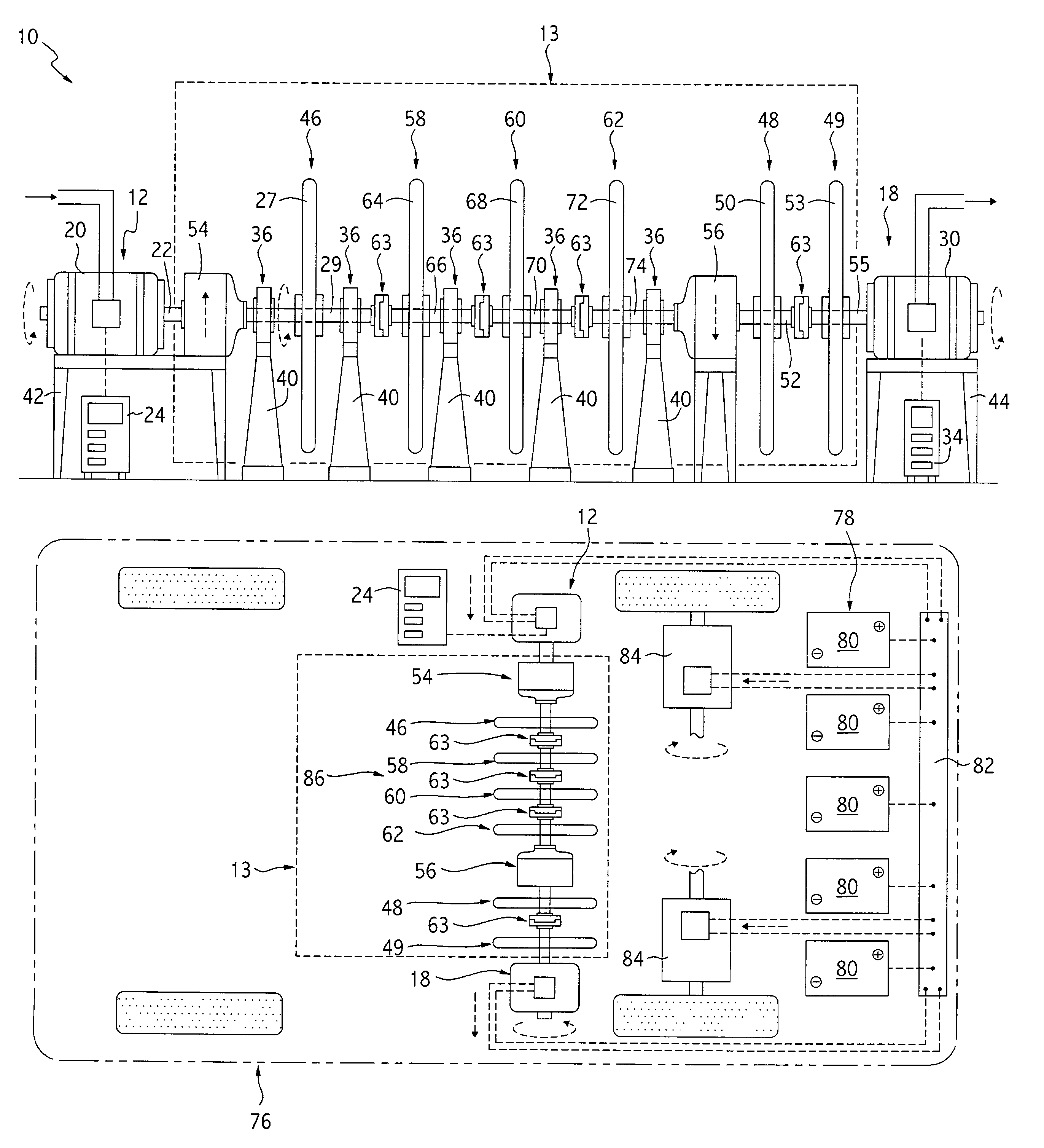
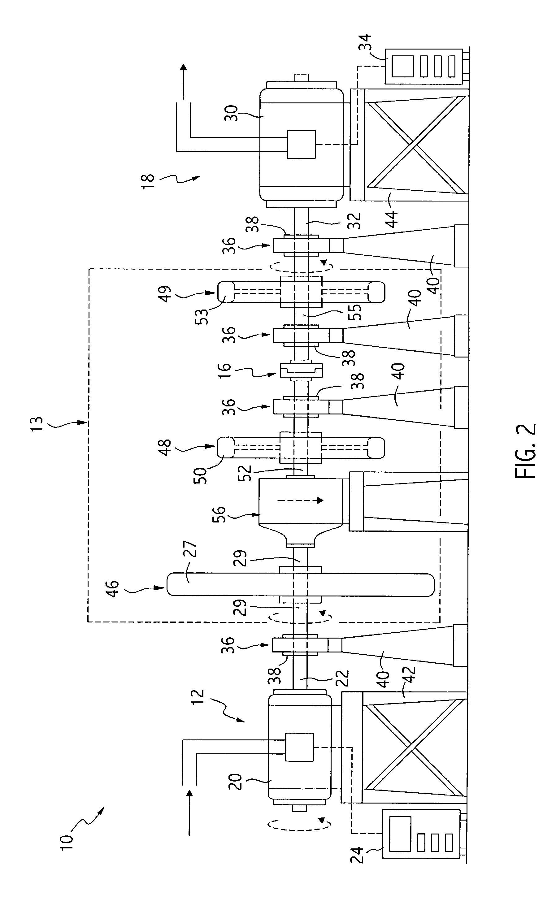
[0027]Referring to FIGS. 3 and 4, the present invention is shown. In this embodiment, the assisted—assisted, torque-enhance gearbox 13 further includes a speed increaser 54. The speed increaser 54 is connected between the motor 20 and the first flywheel assembly 46 and is used to increase the speed of the first flywheel assembly 46 to a speed that is greater than the speed of the motor 20. By increasing the speed of the first flywheel assembly 46, this embodiment increases the amount of energy stored by the first flywheel assembly 46. It is well known in the art that the energy capacity of a flywheel is proportional to the square of the rotational speed of the flywheel. Thus, an increase in the rotational speed of flywheel assembly 46 results in an increase in the energy capacity of the flywheel that is proportional to the square of the increase in speed. The amount of increase can be varied and is dependent upon the energy requirements of a given application.

[0028]The speed increas...

fourth embodiment

[0029]Referring to FIG. 5, the present invention is shown. This embodiment is similar to the embodiment shown in FIG. 3 except that inertia-assisted, torque-enhance gearbox 13 includes, in addition to the first, second, and third flywheel assemblies, 46, 48, and 49, fourth, fifth, and sixth flywheel assemblies, 58, 60, and 62, connected between the speed increaser 54 and speed decreaser 56 using multiple clutch assemblies 63. The fourth flywheel assembly 58 includes a fourth flywheel 64 and a fourth flywheel shaft 66, the fifth flywheel assembly 60 includes a fifth flywheel 68 and a fifth flywheel shaft 70, and the sixth flywheel assembly 62 includes a sixth flywheel 72 and a sixth flywheel shaft 74. The clutch assemblies 63 are similar to the clutch assembly 16 described previously in reference to FIG. 1 except that these assemblies engage and disengage at a much higher speed. For example, in one version of this embodiment, the clutch assemblies 63 engage at approximately 10,000 rp...


PUM


Abstract

A system and method for generating power includes a motor assembly, an inertia-assisted, torque-enhanced gearbox, including a flywheel assembly and a clutch assembly, and a generator assembly. The motor assembly is used to drive the flywheel assembly up to the generator's designed operating speed. When the flywheel assembly reaches the generator operating speed, the clutch assembly engages and connects the flywheel assembly to the generator assembly. When the flywheel assembly is connected to the generator assembly, it supplies the generator with the starting torque required to start the generator. The motor assembly then supplies the torque necessary to operate the flywheel assembly and the generator assembly at the generator's designed operating speed. When the generator encounters peak loads, the flywheel assembly also supplies peak load torques to the generator assembly. The generator assembly is operable to supply power to a load connected to the generator assembly.

Description

BACKGROUND OF THE INVENTION[0001]The present invention relates generally to systems and methods for generating electrical power. More particularly, this invention pertains to a system and method of generating power using one or more flywheels.[0002]Power generation systems are known in the art. For example, U.S. Pat. No. 2,688,704 teaches a conventional power generation system that includes a motor that is directly connected to a generator. The motor is powered by an ac power source and is used to drive the generator at its designed operating speed. The generator, in turn, generates power based on the speed at which the motor drives the generator. The system also includes a flywheel, clutch, and combustion engine, all of which are connected to the generator. If power to the motor is interrupted, the clutch engages and the flywheel, which is rotating at the designed operating speed of the generator and contains a certain amount of kinetic energy, is used to supply power to and start ...

Claims


Application Information

Patent Timeline
Patent Type & Authority Patents(United States)
IPC IPC(8): B60K25/10B60L50/30H02J9/08H02P9/06
CPCB60L11/16H02J9/08H02P9/06Y02T10/7027Y02T10/7033Y02T10/642B60L50/30Y02T10/64Y02T10/70
Inventor WASHINGTON, JERRYWASHINGTON, DEWAYNE
Owner LEGACY IP
Why Eureka
Try Eureka